
Friday Flownex Tech Tips #10
Happy Friday! In today’s tech tip we’ll introduce the rotating components library and demonstrate how to utilize the cavity drawing tool for rotor-stator cavities which can be a huge time-saver when building secondary flow networks. We are working with Flownex version 8.12.7.4334.
Rotating Components
One common implementation of rotating components in Flownex that I see is for modeling secondary flow networks for gas turbines. These flow paths are also sometimes called secondary air systems. What this refers to is the flowpath separate from the primary flowpath (Secondary, get it?). This is flow used to cool equipment, shrouds, discs, vanes, and to provide buffering for the seals to the oil system.

Flownex has a whole library of rotating components that come in handy when building these secondary flow networks. These are well documented in the Flownex help manuals if you’d like to read up on technical specification, inputs, results, and theory.

- Custom Vortex
- A custom vortex is used when velocity profile is between that of a forced vortex and free vortex.
- Forced Vortex
- In a forced vortex the fluid moves similar to a solid body with constant angular velocity.
- Free Vortex
- Free vortex swirl is calculated using mass flow rate average of the incoming swirl streams, swirl is constant over the radius; usually used for rotating fluid in an open cavity.
- Labyrinth Seal
- Used for modeling axial and radial straight and staggered seals.
- Rotating Annular Gap
- Used to model flow through an annulus with the inner or outer cylinder rotating.
- Rotating Channel
- Used for flow inside channels in rotating discs and blades.
- Rotating Nozzle
- Similar to a stationary nozzle where there is a discharge coefficient as a function of the inlet type.
- Rotor-Rotor Cavity
- Used when calculating swirl ratio from moment balance on the the rotor surfaces, bolt heads, and flows.
- Rotor-Stator Cavity
- Used when calculating swirl ratio from moment balance on the the rotor and stator surfaces, bolt heads, and flows.
Cavity Drawing Tool
Now we get to the nitty gritty of todays tip; how to utilize the cavity drawing tool. When we use either a Rotor-Rotor component or a Rotor-Stator component there are two options for specifying the surface geometry. We can either model as pure radial disks, or as a complex surface specification.

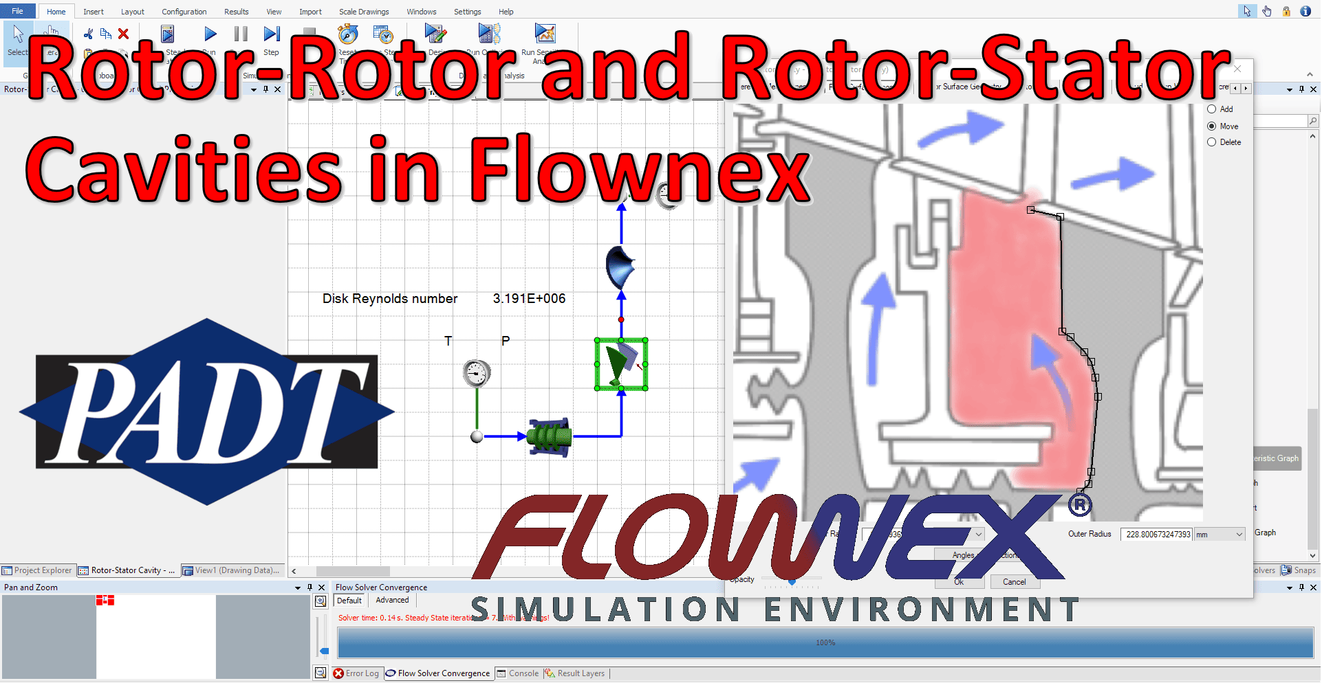
We can use the complex surface specification option to model a rotor-stator cavity like in the cross-section below. When using this option we will need to get a cross-section like this from CAD or from a scaled technical schematic.

To specify this surface geometry we will click the radio button next to surface geometry and add our image to the project. For a refresher on adding an image to your project check out the blog post on adding a background image.

Reference Measurements
We will first need to specify our reference axial and radial coordinates. This is done by dragging the red and blue boxes to known locations on the cross section and entering in the values in our desired units.

Surface Geometry
Now that we have specified the reference measurements we can define our rotor and stator surface geometries. This can be done in the Rotor Surface Geometry ribbon and the Stator Surface Geometry ribbon. The mode in the top right of the GUI lets us know if we are adding points, moving points, or deleting points. To add points we will click and drag from the previous point.

You’ll notice the inner and outer radius fields are automatically updated. This can be a good way to sanity check against known measurements or against CAD. We will need to do the same thing for the stator surface geometry.

Bolts
If there are rotor or stator bolts they may be added in their respective ribbons. The blue lines we see in these images represent the limits of the rotor or stator surface. If bolts are added we will need to click Bolt Details at the bottom of the window and add bolt geometry. The radius fraction is populated automatically and the other inputs will need to be updated as needed by the engineer.

Cavity Shroud
If we need to model the cavity shroud this can be done in the shroud ribbon. In our demonstration today the shroud is included in the rotor and stator surface geometries. For this case we can de-select specify shroud width.

Gap Width
Next we must specify the gap width. To understand what the appropriate width to specify we must dive a little bit into the theory.
Flow regimes for rotor-stator cavity flow can be classified by the following image:

“G” being the gap width ratio (s/a where s is the gap width and a is the outer radius of the cavity) and Re is the Reynolds number for cavity flow. Essentially there are four regimes which are determined by the Reynolds number and gap ratio.
Flownex uses correlations from Haaser et. al (1987) and Daily and Nece (1960) to calculate the required moments produced by the rotor or stator on the fluid within the cavity. Haaser et al. is valid for Regime IV whereas Daily and Nece is valid for 0.0127<=s/a<=0.217 and 1000<=Re<=1e7. It is suggested to use Haaser when the flow is in Regime IV and Daily and Nece when the flow is within the other regions.
I hope I haven’t lost you.
So, for complex geometry (not just two flat surfaces) it is recommended to use the smallest gap width first and calculate the disc Reynolds number. Using the smallest gap width gives you the smallest gap width ratio which will lower the point at which your fluid is in the flow regimes graph above. Now check in what region you are. If your Reynolds number is high enough to be in region IV, and while using the smallest gap width your are still in region IV then it is safe to say that your entire flow will be valid when using Haaser. If this is true, you can then use the smallest gap width because the correlations of Haaser is not dependent on gap width. Using the minimum gap width essentially allows you to make sure that your entire flow is within regime IV. When you have used the smallest gap but see that your gap width ratio and/or Reynolds number leaves you in a different regime (I,II or III), we will then suggest that you calculate the moments using Daily and Nece.
To summarize, start with the smallest gap width and determine the Flow Regime:

If we are in region IV for the smallest gap width then we can leave the gap width as originally specified. If we were in any other region we should change our gap width to be an average:

Don’t forget to specify the correct correlation in the inputs for your rotor stator cavity as well. Big thanks to Leander Kleyn at Flownex for helping me understand the theory behind the gap width!
Discretization of the Cavity
Lastly, we need to assign the discretization of the model. This can be thought of as sort of refining the mesh of the cavity. We can specify more or less increments and can drag the increments around to be sure to capture changing geometry.

There you have it! A complex surface specification of a rotor-stator cavity using the cavity drawing tool in Flownex!


