
Flownex Friday Tech Tips!
Today I’m going to go through my workflow of modeling a fire suppression system in Flownex. This particular system is designed with an aircraft in mind. We’ll go over typical workflow and transient setup using Flownex version 8.12.8.4472
Background Image
See my post on adding a background image for in-depth step-by-step direction. I first set up a background image so I have an easily understood flow schematic to reference in my Flownex build. This also is particularly useful when showing or passing the network off to a colleague or customer who may not have intimate familiarity with Flownex. The image I used in this demo is from this paper by Jaesoo Lee.

Choosing the Appropriate Flow Components
In this model I’ve got a storage bottle, a distribution pipe, and some injection nozzles. I know that I want this to be able to handle two-phase and I know I am pressurizing the bottle with N2 so I will use the Container Interface components to represent the bottle. I will use pipe components for the distribution line, and for the nozzles I will simply use restrictors with discharge coefficients.

Container Interface – Top

Container Interface – Bottom

Pipe

Restrictor with Discharge Coefficient
Building network of components and entering geometry
While building this network I realized I was missing one additional component. I needed to add a valve to open the bottle and release the fire suppressant (HFC-125) and a valve representing a vent to the top portion of the tank which we will leave fully closed.

We need to specify our initial pressures, mass fractions, and a temperature on the storage bottle. We also need an outlet pressure and temperature to fully constrain our model. I use a “view” node on my nozzle so that I only need to specify a single outlet boundary condition.
Transient setup
For this transient analysis I am going to open the valve and see how quickly the suppressant discharges from the system. The first thing we will want to do is to remove any boundary conditions that we want to be “free” during the transient. I’ll remove all of the boundary conditions at the storage bottle so that Flownex will calculate the remaining pressure as our system discharges.

I also need to specify our timestep and simulation length. We can do this under the Scheduler properties which can be found in the Solvers pane on the right side of the GUI. I chose a timestep size of 20ms and a total simulation duration of 2 seconds.

Solve Steady State, Snap and Run!
To get a stable transient simulation it’s best to start from a converged steady state. At this point I’ll solve steady state, addressing any warnings that arise. Then we will want to save a Snap of the solve (so that we can load the snap to get back to initial conditions for any future transient runs).

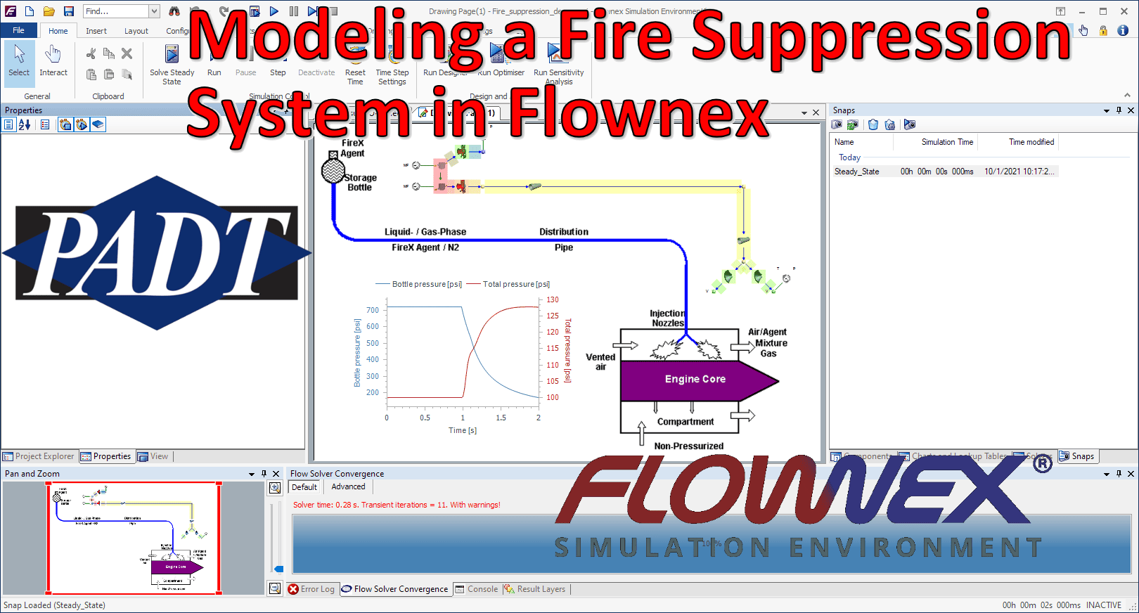
At this point we should be good to run our transient analysis! I’ve added a plot of the pressure in the bottle and pressure just before the nozzles vs time to this project as well:


