
Ansys Zemax Composite Surface Introduction
In 2022 R2.02, Ansys Zemax OpticStudio (AZOS) released a powerful new feature that enhances tolerancing capabilities and expands the possibility of simulation and analysis of optical systems. The Composite Surface is available in sequential mode as a tool to add multiple sag profiles or perturbations to any sag-based surface as a Composite Stack. Complex surface geometries are now easier than ever to create in sequential mode without the need for complex workarounds.
Not only can surface perturbations be added manually to any sag-based surface with the use of this new feature, but the tolerancing capabilities of existing surface irregularity operands, TIRR, TEXI, and TEZI have expanded by leveraging Composite Surfaces. Previously these operands were limited to 1-3 surface types, now, a surface that qualifies as a Composite Surface can utilize these operands.
The full list of surfaces that support the Composite Surface features has been provided by the Ansys Zemax team in the Introduction to Composite Surface – Knowledgebase (zemax.com) article and are listed below:
- Biconic
- Biconic Zernike
- Chebyshev Polynomial
- Even Asphere
- Extended Asphere
- Extended Odd Asphere
- Extended Polynomial
- Grid Sag
- Irregular
- Odd Asphere
- Odd Cosine
- Off-Axis Conic Freeform
- Periodic
- Polynomial
- Q-Type Asphere
- Q-Type Freeform
- Standard
- Superconic
- Tilted
- Toroidal
- Zernike Fringe Sag
- Zernike Standard Sag
- Zernike Annular Standard Sag
Optimizing an Afocal Off-Axis System using Off-Axis Conic Freeforms
As an example to show how the Composite Surface enables users to manually perturb a surface, let’s look at this 5x off-axis afocal system from Warren Smith’s Modern Lens Design.

The off-axis system is a classical Cassegrain telescope with a concave mirror acting as the “eyepiece” of the system. As is, the system is free of spherical, coma, and astigmatism, however, there are higher order aberrations such that the Optical Path Difference (OPD) has a scale of 0.5 waves for the full field in the f, D, and C lines of the visible spectrum.

To optimize the system, the second and third mirrors were replaced with Off-Axis Conic Freeform surfaces which provide more degrees of freedom to improve system performance. After replacing the mirrors, the system performance and global coordinates of the mirrors should match that of the original design since we are only converting the surface type and have not started the process of optimizing the system. The Lens Data editor should now look like the following:

The 3D Layout, OPD Fan, and Global Vertex Data can help determine if the Standard surfaces have been accurately replaced by the Off-Axis Conic Freeforms. All three should match the system prescription and performance before and after the switch. The 3D layout and OPD Fans should provide quick checks that could hint at any offsets or issues while the Global Vertex Data can verify that the location of each surface has not changed. The Global Vertex Data can be found within the Prescription Data Report:

The system was optimized by utilizing the Optimization Wizard with the function criteria Angular so that the merit function computes the angular aberrations in image space given that the system is an afocal system. The radii of all 3 mirrors, the thickness between mirrors, and the conic constants of all three were optimized (with the use of constraints to keep the overall length of the system close to the original and the conic constants between -10 and 10). For the two Off-Axis Conic Freeforms, the power, astigmatism, spherical, and coma terms were also variables in the optimization.
Thus, a total of 24 terms were used to optimize the system. Because this article is meant to highlight the new Composite Surface feature, I will refrain from detailing the full optimization technique used to improve the performance of the system, however, I think it is important to note that not all 24 terms were used as variables at once, and there were a couple of iterations of merit functions to obtain the final system design.

The optimized system looks identical to the original system in the 3D layout window, however, the OPD fan will show the performance improvements due to the Off-Axis Conic Freeforms.


How to Utilize Composite Surfaces to Tolerance Off-Axis Conic Freeforms
Although the Composite Surface has expanded the capabilities of the TIRR, TEXI, and TEZI tolerancing operands, the operands currently do not support off-axis apertures. However, the Composite Surface still allows for a workaround that directly adds perturbation to the mirror surfaces in the Lens Data Editor.
The TIRR tolerancing operand is used to analyze the effects of surface irregularity, and prior to the Composite Surface feature, was only available for the Standard Surface. In AZOS, the operand assumes that the surface irregularity is equally split between spherical aberration and astigmatism. This is because surface irregularity is usually hard to predict or determine compared to the other system tolerances.
To manually contribute surface irregularity from the Off-Axis Conic Freeforms within the optimized afocal system, an Irregular surface is added to the Lens Data Editor just before the Off-Axis Conic Freeform.

In the Surface Properties of the Irregular surface, The Composite Tab has the option to add the sag of the surface onto the next surface:

The Irregular Surface is now considered the Composite Add-on, while the Off-Axis Conic Freeform is the Composite Base. Both the Composite Add-On and Composite Base make up the Composite Stack. Because the Base is an off-axis surface with tilts and decenter, it is important to select the “Set Tilt/Decenter to follow Base Surface Aperture” on the Composite settings of the Add-On surface.
Once surfaces are part of a Composite Stack, they are highlighted in yellow in the Lens Data Editor.

The spherical aberration and astigmatism can now be added onto the Off-Axis Conic Freeform to analyze the effects of surface irregularity on the system. Perturbations in respect to tilt can also be included via the Irregular surface.

The surface sag is added to the Off-Axis Conic Freeform, and the effects on the optical performance can be visualized in the analysis windows. For example, after adding 1 µm of spherical aberration to the surface, the performance of the system is degraded as seen on the OPD plots:

Understanding the effects of surface irregularities can be critical in meeting optical performance criteria.
Visualizing the Composite Stack with the Sag Map & Cross Section
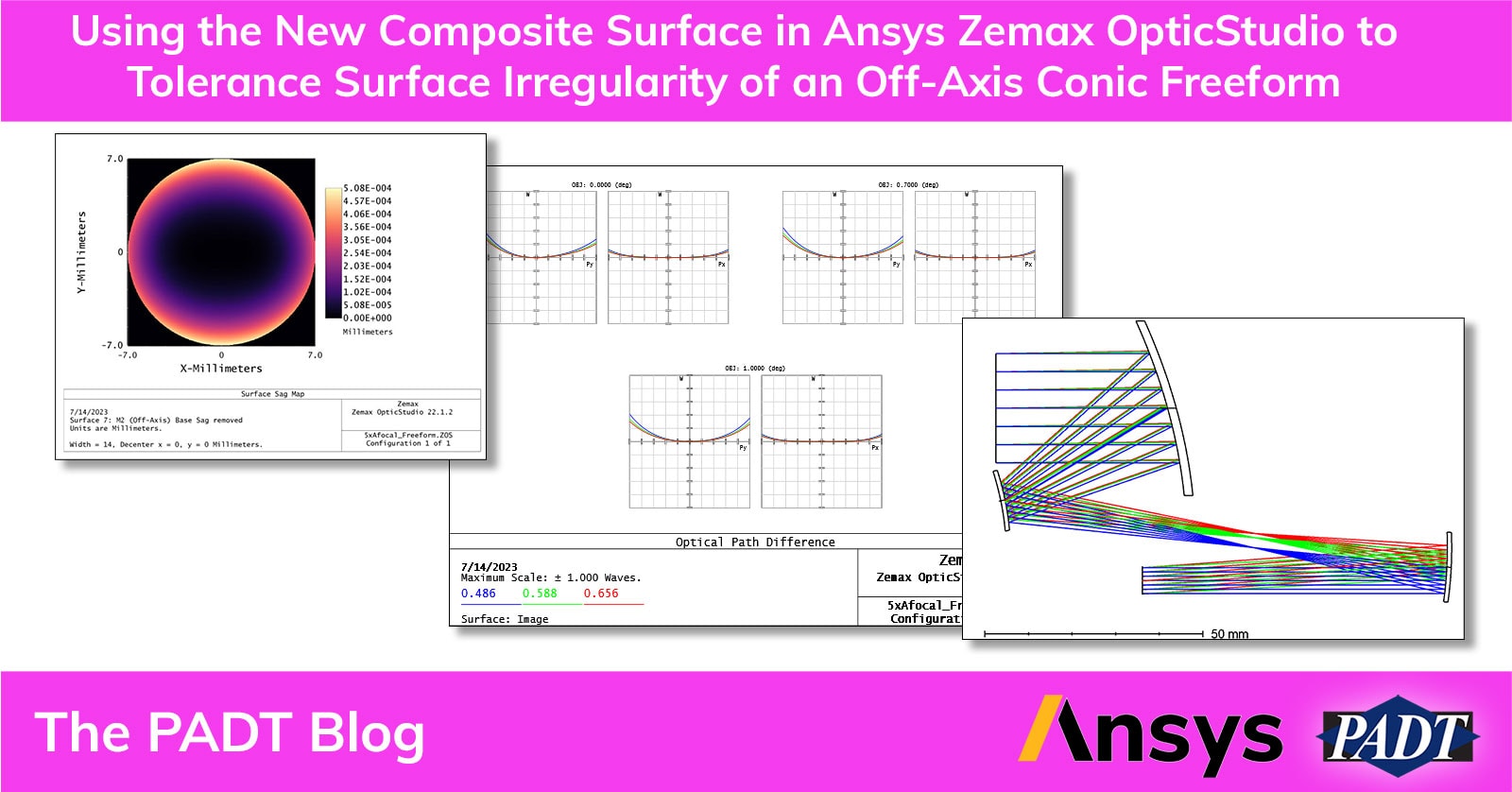
The effects of the Irregular Surface parameters on the Composite Base can be visualized using the Surface Sag and Surface Sag Cross Section analysis windows. Users have the option to remove the Base Sag or the Composite Sag in the Surface Sag windows:

For this example, the Composite Sag is much lower than the Base Sag since we are incorporating surface irregularities that tend to be a fringe or smaller. Removing the base sag from the Surface Sag map will visualize the sag of the Composite Add-On.

The example above shows the Irregular surface sag with 100 um of both spherical aberration and astigmatism. The OPD fan shows the effect of the added surface irregularity:

The size of the surface irregularity in this example is higher than what is expected in a real mirror, but the amplitude of the aberrations can be adjusted to understand how sensitive the system is to these perturbations to notify the manufacturer of each allowable surface tolerance.
Even though this technique is not automatic through the Tolerancing Analysis tools within AZOS for off-axis apertures, this workaround should provide some insight into the sensitivity of off-axis surfaces like the Off-Axis Conic Freeform.
Conclusion
The Composite Surface feature available in Ansys Zemax OpticStudio is a powerful tool that opens a new realm of possibility in optical design and tolerance analysis. If you have any questions on this new feature or how to incorporate an Off-Axis Conic Freeform into your design, let us know! We would love to help!
As always, please feel free to reach out to us here at PADT for more information on Ansys Zemax OpticStudio, other Ansys Optics products like Ansys Speos and Ansys Lumerical, as well as any other of your simulation needs!
Here are the files we used for this blog post:
References
- C. Gu. Introduction to Composite Surface. support.zemax.com. Accessed July 14, 2023. Introduction to Composite Surface – Knowledgebase (zemax.com).
- W. J. Smith. Modern Lens Design. 2nd Edition.


