
I know…been a while. Finally had the chance to sit down on a support case with an interesting behavior that has a not-exactly-intuitive fix. Let’s talk about remote objects…
So, remote objects (point masses, remote points, body-body connections, etc) are a great way to define loads/constraints for features not explicitly modeled in your Ansys Mechanical simulation. Behind the scenes, it creates a pilot node that interacts with a group of constrained nodes in your model.

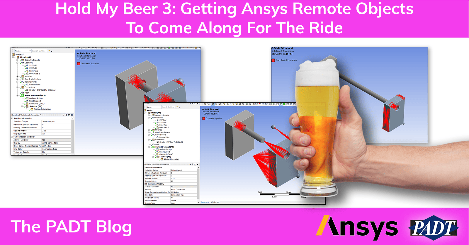
The image above shows the constraint equations generated for a body-body beam, a remote point scoped to a face, a point mass scoped to an edge, and a point mass scoped to a point.
How Do We Get Remote Objects to Behave? Well, Hold My Beer, and I’ll Show You
So, what happens when I change the spacing of the two blocks. You might expect everything to work just fine since everything is persistent in Mechanical (assuming you’ve properly saved the CAD geometry if you’re using an associative interface or if you’re passing everything through SpaceClaim or Discovery…or DM if you like to roll that way).

Went from 10 mm of separation to 20. Update in Mechanical:

Well. That’s certainly not what I wanted. So let’s dig into what happened.
The main culprit here is that remote objects that do not use a direct attach don’t update their location. Let’s dig into what that means…
The point mass on the bottom corner is directly connected to a point. There are no constraint equations generated, that element is defined from the node on the block:

All other objects in the model connect through constraints and have more going on in the ‘scoping’ portion of the details window:

Highlighted in yellow, that controls what nodes are constrained to the pilot node. You don’t have to worry about refining/coarsening the mesh on that face, when you hit solve the nodes on that face are paved with target elements and constrained to the pilot node.
Bracketed in red is *where* the pilot node is located. When you first insert a remote point it defaults to the centroid of what you’re attaching it to. It automatically fills out the x/y/z location in the global coordinate system. However…this is a one-time operation. It doesn’t re-do the location on any other update. Before you start complaining…the location is an absolute value and you can over-ride the location by typing in new x/y/z values.
So the solver doesn’t know if this is where the remote object is always located, or if it’s always relative to the selected face. ANSYS defaults to the assumption “this location is where the remote object always exists”. What we need to do is re-define the location to be a relative definition.
So…how do we do that. First, we need to create a coordinate system based on the geometry we’re attaching to:

Select the geometry, right-mouse-click, create a coordinate system. Repeat that for all the remote objects you need to follow the geometry (note I’m not doing this for the left-side of the body-body beam). Here’s why…user coordinate systems will update when the geometry changes:

Now, go back and redefine the remote objects to be 0,0,0 at that user coordinate system:


Alright, now let’s verify the behavior with some geometry updates:

Gives me:


Gives me:

There ya go! We get a remote object to follow its geometry by making sure the location is defined in a user-coordinate system scoped to that face.
There’s More From Where This Came From
If you found this useful, check out the other “Hold My Beer” posts. Or check out other useful posts on our blog. If you want to work with engineers who know their Ansys, wether for support or for consulting, contact us, let’s talk.


