Introduction
Welcome to the 21st century, folks. Where software updates are required for everything from cars to laptops, to lights, and more! That’s just the way it goes… software runs just about everything. Speaking of software, PADT offers sales and support for one of the most powerful development environments out there. SCADE (Safety Critical Application Development Environment) is the latest piece of the ANSYS pie to be supported by us, and I would love to share some insight into how it can improve the workflow for software engineers, maintenance teams, end-users and more.
While there is rarely one piece of software capable of doing all the work for you, one might be interested in a piece of software which generates certified C or ADA code on the fly. This is where SCADE comes in play. The SCADE tool is a visual and model-based tool which generates functional code for a wide variety of uses and industries, from aerospace to power generation, and even robotics. Based on my background in robotics, I wanted my first project to be rooted in what I was comfortable with, building a robotic arm to take over the world…*cough cough* I mean pick up objects on a table.
If you’ve made it this far, and understand some of the technical jargon above, you’re probably familiar with the fact that there are nearly infinite ways to do the same task in code, and this stays true in SCADE. While there are best practices to follow, we can use this project as a learning opportunity, rather than making the most efficient SCADE model. Fortunately for us, SCADE takes into consideration all the code from start to finish and generates the most efficient code possible to run on embedded systems like a microcontroller or FPGA. This multi-part tutorial will take us on a journey of building robotic control logic and seeing how it plays out on physical hardware.
SCADE Initial Setup
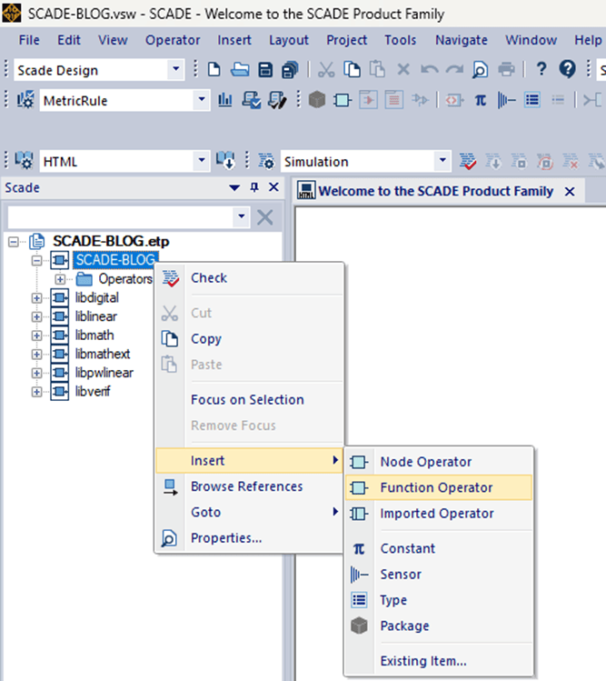
First, we should start with a basic set of control logic, to set servos to different positions instantly. To do this, create a new SCADE Suite Project in 2023R2. Then, we can create a new function operator in the top level of the project:
Next use the ribbon bar to add an input, output, and textual expressions like so:

Be sure to change the input type to “char” in the properties tab.

You can leave the output type as default, “int32”.

We’ll need to add n+1 textual expressions vs desired, as one will be a “default” value, in case the input is unexpected.
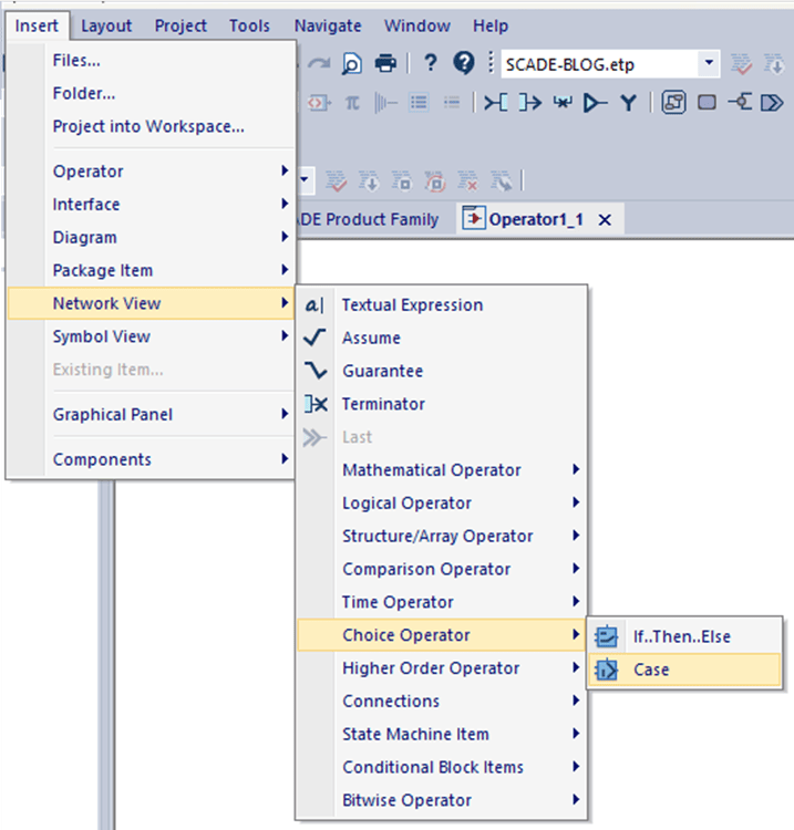
Finally, we’ll add a case operator (with associated textual expressions) to get the desired functionality:
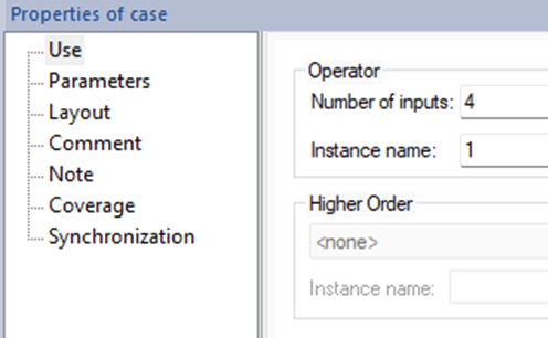
In this case, we’ll use 4 inputs. (3 outcomes + 1 “Default” value)
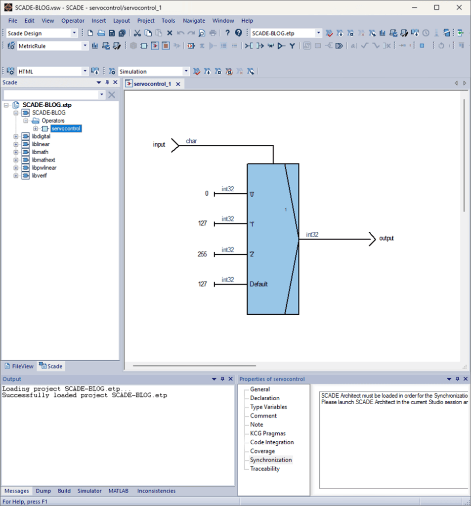
From there, edit the diagram to connect the input to the top of the case operator, the output to the right-hand side, and the textual expressions to each of the left-hand sides. Change the inside of the case operator to have different values. In this case, we can use ‘0’, ‘1’, ‘2’. If everything went according to plan, the diagram should look like this!
Simulate, Simulate, Simulate
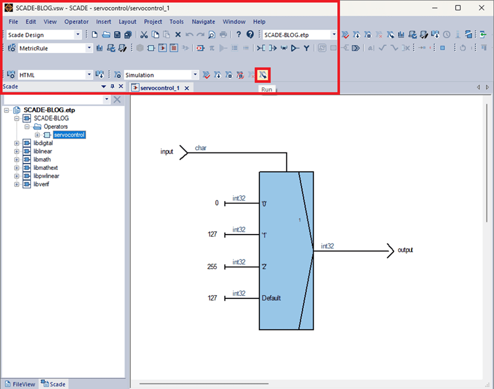
To test the functionality of the code, you can simulate the code inside a virtual environment, which is extremely helpful for debugging projects, and understanding the innerworkings of the code. You can do so by starting it here:

To understand how the outputs change based on the inputs, go ahead and run the simulator and change the input value on the left-hand sidebar, like so (Note that input is declared as a “char” data type, so values require apostrophes around them, otherwise only the “Default” value will be triggered):
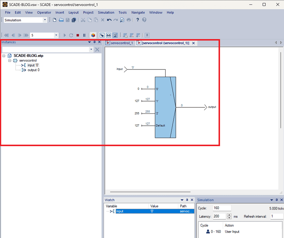
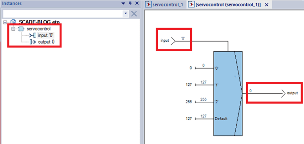
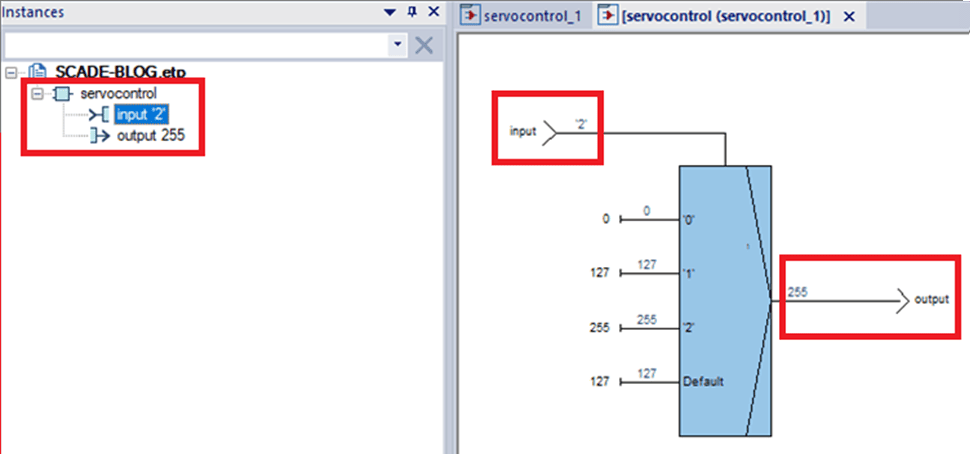
Notice how the output value is changing based on the changed input value.
Multi-Servo Functionality
After getting this working, we should “Map” the controls across a broader range of servos. From one servo to three… just to show how the functionality works. Depending on your use case and parts on hand, you may want to increase or decrease the number of controlled servos.
First, select all contents of the diagram, except for the input and output.
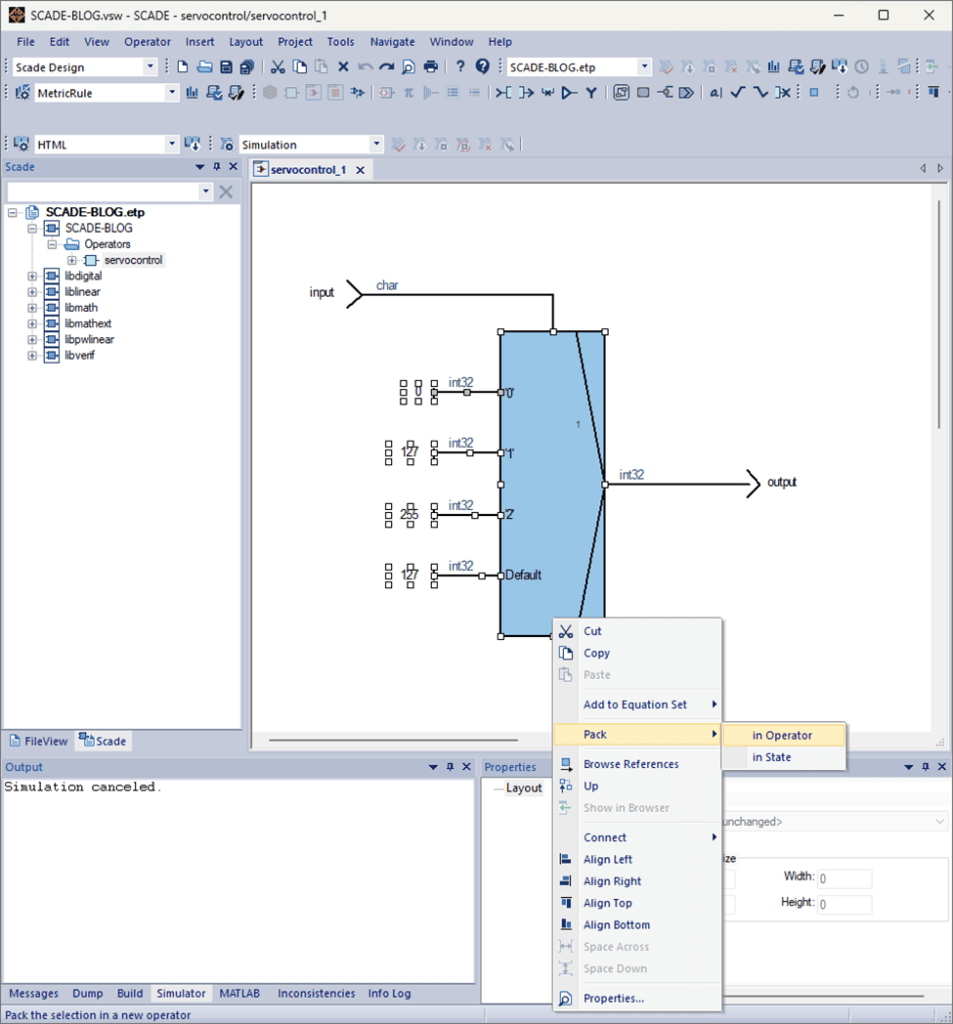
Go ahead and apply a higher order “map” to the operator like so:
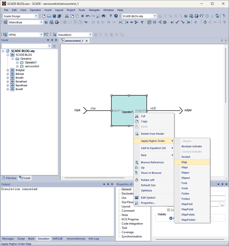
In the properties tab, adjust the array bounds to 3 and adjust the data type of the input and output to char^3 and int32^3, respectively. We should also declare “Operator1” to be a function, rather than a node, as this operator has no internal memory. These changes will allow everything to work together and allow each servo to have a different value.
More Simulation!
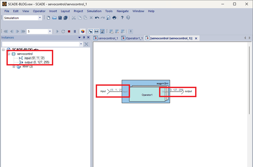
When simulating, you can see different output values (0, 127, 255) for each servo based on the varied inputs (‘0’, ‘1’, ‘2’).
Conclusion
Congratulations, you made it! If you’ve followed this long, you’ll be happy to know that we will run this code on physical hardware in our next SCADE blog post. Here is a link to our SCADE repository on GitHub, so you can access associated files. If you have questions about SCADE, or any other ANSYS products please get in contact with us. We’d love to hear from you.
This is Noah, signing out. Have a great day.

