
With the release of 2023 R2, the Ansys LS-Dyna interface in Ansys Mechanical can now specify a thin volume to be meshed with either a standard hexagonal solid element or using a thick shell element formulation using the Multizone (thin sweep decomposition type) mesh method.
For those familiar with implicit ANSYS Mechanical, a similar element is referred to as a solid-shell element (SOLSH190). This element type is very popular in implicit ANSYS structural applications for modeling thin volumes that are too thick to be modeled with traditional thin shell formulations and computationally expensive to mesh with standard hexagonal or tetrahedral elements to capture accurate bending behavior.
The appeal does not stop there. The SOLSH190/Thick Shell uses a low-order hexagonal element topology having 4 nodes on the top and bottom face of the element with three degrees of freedom at each node. The element formulation is based on logarithmic strain and true stress measures and allows loads and boundary conditions to be uniquely applied to the top and bottom surfaces of the elements.
In Ansys LS-DYNA, this element has several formulations:

Per user manual remarks “Thick shell element formulations 1, 2 and 6 are extruded thin shell elements and use thin shell material models and have an uncoupled stiffness in the z-direction. Thick shell element formulations 3, 5, and 7 are layered brick elements that use 3D brick material models. Thick shell formulations 3 and 5, and 6 are distortion sensitive and should not be used in situations where the elements are badly shaped. A single thick shell element through the thickness will capture bending response, but with thick shell formulation 3, at least two elements through the thickness are recommended to avoid excessive softness. “
In the Ansys Mechnical/Ansys LS-Dyna implementation, the element formulation is set to option 5 (assumed strain reduced integration with brick materials). Thick shell elements of all formulations can be used to model layered composites, but element formulations 5 and 6 use assumed strain to capture the complex Poisson’s effects and through thickness stress distribution in layered composites.
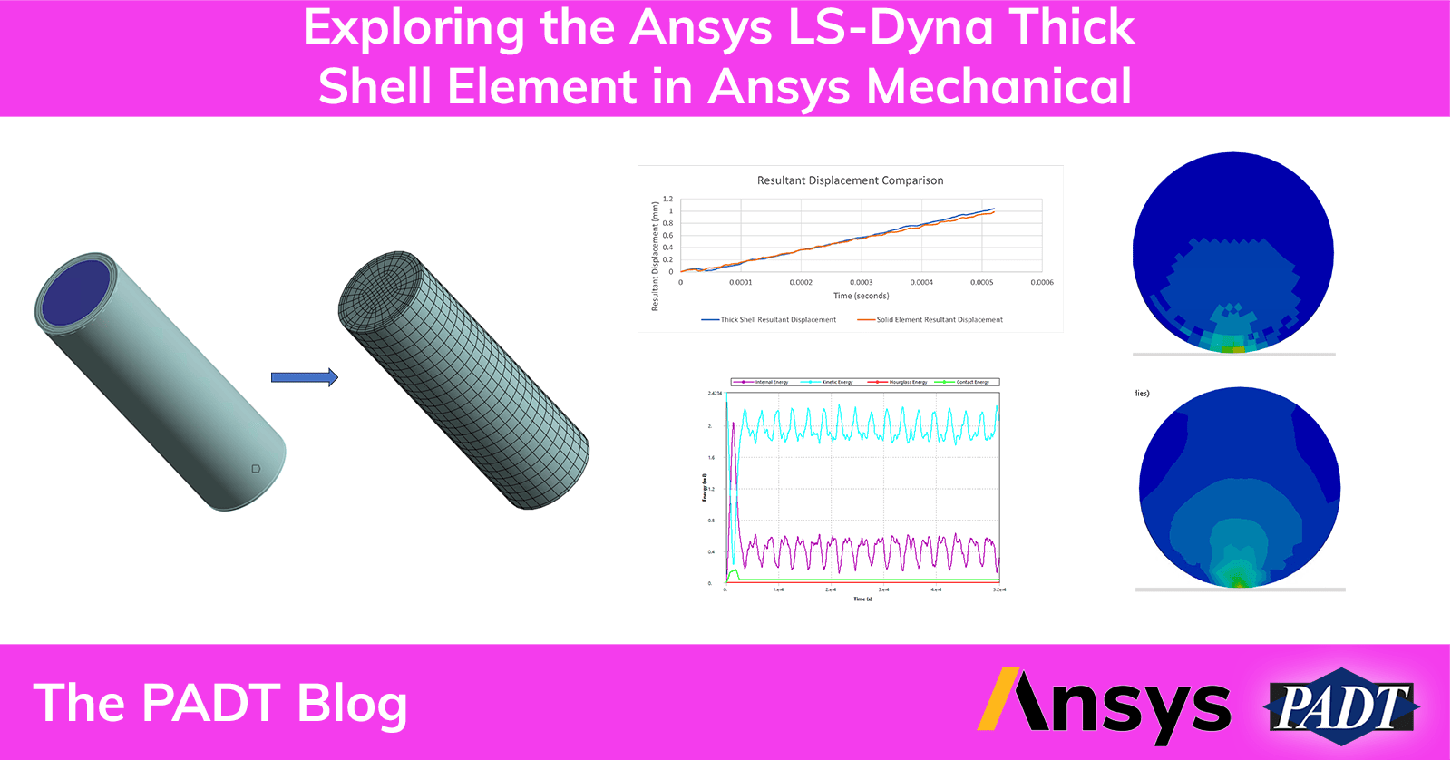
Exposure of this element type allows for some applications to significantly reduce the analysis time needed to evaluate a given design. To demonstrate how to access this new mesh option, we will be comparing and contrasting a double wall aluminum cylinder dropped onto concrete from a height of 12 inches using both thick shells and traditional full integration S/R solids.
This demo model uses the drop test wizard to set up the orientation of the cylinder for a side drop, calculate the equivalent impact velocity based on the drop height provided and create the impacting floor at the onset of contact, assigned to rigid concrete in this example.
Ansys LS-Dyna Demo Model Definition:
- Aluminum 6061 T6 double wall cylinder – 8mm diameter, 50mm long and wall thickness of 0.25mm
- Concrete Floor – 30mm x 30mm x 0.50 mm thick (modeled as rigid part)
- 304.8mm (12 inches) drop height.

Figure 1: Demo Model Geometry Reference (1/2 section)
The exposure of the thick shell in Ansys Mechanical/Ansys LS-Dyna uses the same mesh method as implicit ANSYS to mesh the SOLSH190. The “MultiZone” method when set to Decomposition Type– thin sweep and the Element Option – Solid Shell creates *ELEMENT_TSHELL elements in Ansys LS-Dyna keyword format.


In the 2023 R2 release the Source Scoping Method was hardwired to be Program Controlled which did not always work when the mesher could not determine the thickness or the source and target surfaces for certain volumes. In release 2024 R1, the option to define both Manual Source(s) and Target(s) was added and has greatly enhanced the robustness of getting a successful mesh.

V2023 R2 MultiZone Details Menu

V2024 R1 MultiZone Details Menu
The default number of through thickness integration points set for this element type is 2 unless the user inserts a Section object to specify up to 9 integration points.

There is one more 2024 R1 feature related to meshing that was used on this topology for the thick shell version of the model. When meshing circular volumes, it is often necessary to use a pave option for the surface mesh to prevent small elements from being generated. The thick shell is more sensitive to mesh shape quality as well, so a new feature was used. In release 2024 R1 the Face Meshing object has a new beta feature added. This option produces a high-quality mesh transition without the need for manual decomposition.


The mesh and element type for the concrete floor was exactly the same, so the only difference in the two configurations was element type and mesh density for the double wall cylinder.
For the thick shell version of the cylinder, the mesh size was set to 0.50 mm and produced 11808 nodes and 5954 thick shell elements. The run time was 6m and 38s running on 15 SMP cores with a starting integration time step of 2.37e-8 seconds, consuming a maximum of 37GB of RAM. This model run on 1 SMP core took 12m and 8s. All versions of the model were run using Ansys LS-DYNA executable version 14.1-205-geb5348f751 (Version delivered with Ansys Mechanical/Ansys LS-DYNA V2024 R1)


Figure 2: Thick Shell Mesh Images
For the solid element version of the cylinder, the mesh size was set to 0.1mm and produced 461,895 nodes and 333825 solid elements. The run time was 3hrs 8m running on 15 SMP cores with a starting integration time step of 4.98e-9 seconds consuming a maximum of 77GB of RAM.


Figure 3: Solid Element Mesh Images
Let’s look at some result comparisons starting with energy summary quantities. The most noticeable difference is in the contact energy, the thick shell version has a higher contact energy likely due to a coarser mesh density relative to the solid element version in representing the cylindrical shape. The thick shell uses a reduced integration formulation so some hourglassing energy is expected. The solid element model uses a full integration formulation so no hourglass energy is produced.

Figure 4: Thick Shell Energy Quantity Summary

Figure 5: Solid Element Energy Quantity Summary
Next, if we look at the peak resultant displacement (which includes both elastic and rigid body displacement) we see a good comparison. With the cylinder impacting on the side a hertzian contact zone is developed.


Figure 6: Resultant Displacement at Initial Impact
Looking at the peak Von Mises Stress from each model, we see a slight delay with reduced magnitude in the thick shell model (again likely attributable to mesh discretization) as compared to the solid element model.

The difference in peak stress also translates to a difference in equivalent plastic strain levels. However, the focus of this blog is not to discuss the nuance differences between solids and thick shells, but rather the time savings of using thick shells over solids in obtaining a design evaluation in minutes versus multiple hours of run time for topologies that are appropriate for thick shells.
One aspect of the post-processing that is worth discussing between the solid and thick shell versions of the models is the integration point result setting for derived quantities. In the Ansys Mechanical/Ansys LS-Dyna environment, the default setting for derived quantities like stress and strain is to not average integration point results.
For a model constructed of solid elements of sufficient density, the difference between averaged and non-averaged will ideally be zero, which is the case with the solid element version of this model. For the thick shell version of the model, aspect ratio limitations will prevent convergence of averaged and unaveraged integration results and therefore the default Unaveraged display option should be used to obtain the true peak. Although using the Averaged display option produces a visually more continuous contour, it does not report an accurate peak for the thick shells as shown below.


Figure 7: Comparison of Unaveraged vs Averaged IP Results for Thick Shell
In summary, exposure of the thick shell element formulation in Ansys Mechanical/Ansys LS-Dyna provides for a very fast and convenient way to mesh moderatelly thick volumes with thick shells and saves significant computation time for topologies appropiate for this element type.


