
For those who are not already familiar with it, Discovery Live is a rapid design tool that shares the Discovery SpaceClaim environment. It is capable of near real-time simulation of basic structural, modal, fluid, electronic, and thermal problems. This is done through leveraging the computational power of a dedicated GPU, though because of the required speed it will necessarily have somewhat less fidelity than the corresponding full Ansys analyses. Even so, the ability to immediately see the effects of modifying, adding, or rearranging geometry through SpaceClaim’s operations provides a tremendous value to designers.
One of the most interesting features within Discovery Live is the ability to perform Topology Optimization for reducing the quantity of material in a design while maintaining optimal stiffness for a designated loading condition. This can be particularly appealing given the rapid adoption of 3D printing and other additive manufacturing techniques where reducing the total material used saves both time and material cost. These also allow the production of complex organic shapes that were not always feasible with more traditional techniques like milling.
With these things in mind, we have recently received requests to demonstrate Discovery Live’s capabilities and provide some training in its use, especially for topology optimization. Given that Discovery Live is amazingly straightforward in its application, this also seems like an ideal topic to expand on in blog form alongside our general Discovery Live workshops!
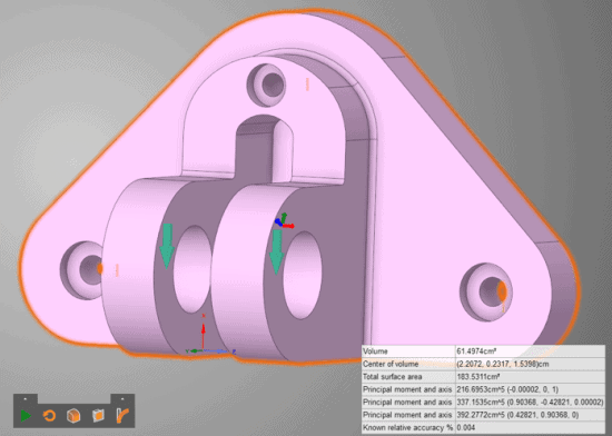
For this example, we have chosen to work with a generic “engine mount” geometry that was saved in .stp format. The overall dimensions are about 10 cm wide x 5 cm tall x 5 cm deep, and we assume it is made out of stainless steel (though this is not terribly important for this demonstration).

Figure 1: Starting engine mount geometry with fixed supports and a defined load.
The three bolt holes around the perimeter are fixed in position, as if they were firmly clamped to a surface, while a total load of 9069 N (-9000 N in X, 1000 N in Y, and 500 N in Z) is applied to the cylindrical surfaces on the front. From here, we simply tell Discovery Live that we would like to add a topology optimization calculation onto our structural analysis. This opens up the ability to specify a couple more options: the way we define how much material to remove and the amount of material around boundary conditions to preserve. For removing material, we can choose to either reduce the total volume by a percent of the original or to remove material until we reach a specific model volume. For the area around boundary conditions, this is an “inflation” length measured as a normal distance from these surfaces, easily visualizable when highlighting the condition on the solution tree.

Figure 2: Inflation zone shown around each fixed support and load surface.
Since I have already planned out what kind of comparisons I want to make in this analysis, I chose to set the final model volume to 30 cm3. After hitting the simulate button, we get to watch the optimization happen alongside a rough structural analysis. By default, we are provided with a result chart showing the model’s volume, which pretty quickly converges on our target volume. As with any analysis, the duration of this process is fairly sensitive to the fidelity specified, but with default settings this took all of 7 minutes and 50 seconds to complete on my desktop with a Quadro K4000.


Figure 3: Mid-optimization on the top, post-optimization on the bottom.
Once optimization is complete, there are several more operations that become available. In order to gain access to the optimized structure, we need to convert it into a model body. Both options for this result in faceted bodies with the click of a button located in the solution tree; the difference is just that the second has also had a smoothing operation applied to it. One or the other may be preferable, depending on your application.

Figure 4: Converting results to faceted geometry

Figure 5: Faceted body post-optimization

Figure 6: Smoothed faceted body post-optimization
Though some rough stress calculations were made throughout the optimization process, the next step is typically a validation. Discovery Live makes this as a simple procedure as right-clicking on the optimized result in the solution tree and selecting the “Create Validation Solution” button. This essentially copies over the newly generated geometry into a new structural analysis while preserving the previously applied supports and loads. This allows for finer control over the fidelity of our validation, but still a very fast confirmation of our results. Using maximum fidelity on our faceted body, we find that the resulting maximum stress is about 360 MPa as compared to our unoptimized structure’s stress of 267 MPa, though of course our new material volume is less than half the original.

Figure 7: Optimized structure validation. Example surfaces that are untouched by optimization are boxed.
It may be that our final stress value is higher than what we find acceptable. At this point, it is important to note one of the limitations in version 2019R3: Discovery Live can only remove material from the original geometry, it does not add. What this means is that any surfaces remaining unchanged throughout the process are important in maintaining structural integrity for the specified load. So, if we really want to optimize our structure, we should start with additional material in these regions to allow for more optimization flexibility.
In this case, we can go back to our original engine mount model in Discovery Live and use the integrated SpaceClaim tools to thicken our backplate and expand the fillets around the load surfaces.

Figure 8: Modified engine mount geometry with a thicker backplate and larger fillets.
We can then run back through the same analysis, specifying the same target volume, to improve the performance of our final component. Indeed, we find that after optimizing back down to a material volume of 30 cm3, our new maximum stress has been decreased to 256 MPa. Keep in mind that this is very doable within Discovery Live, as the entire modification and simulation process can be done in <10 minutes for this model.

Figure 9: Validated results from the modified geometry post-optimization.
Of course, once a promising solution has been attained in Discovery Live, we should then export the model to run a more thorough analysis of in Ansys Mechanical, but hopefully, this provides a useful example of how to leverage this amazing tool!
One final comment is that while this example was performed in the 2019R3 version, 2020R1 has expanded Discovery Live’s optimization capability somewhat. Instead of only being allowed to specify a target volume or percent reduction, you can choose to allow a specified increase in structure compliance while minimizing the volume. In addition to this, there are a couple more knobs to turn for better control over the manufacturability of the result, such as specifying the maximum thickness of any region and preventing any internal overhangs in a specified direction. It is now also possible to link topology optimization to a general-purpose modal analysis, either on its own or coupled to a structural analysis. These continued improvements are great news for users, and we hope that even more features continue to roll out.


