Editors note: For over ten years, this article has been PADT’s most popular post. This shows how powerful the APDL language is and how building Ansys Mechanical on top of MAPDL was a good move. We have recently updated it a bit, and added some additional links at the bottom that you should check out, including an interview with John Swanson, the man who invented APDL. – 7/20/2022
One of the most powerful things about ANSYS Mechanical is the fact that it creates an input file of APDL commands that is sent to ANSYS Mechanical APDL (MAPDL) to solve. This is awesome because you, as a user, have complete and full access to the huge breadth and depth available in the MAPDL program. MAPDL is a good old-fashioned command-driven program that takes in text commands one line at a time and executes them. So to access all those features, you just need to enter in the commands you want.
For many older users, this is not a problem because we grew up using the text commands. But new users did not get the chance to be exposed to the power of APDL (ANSYS Parametric Design Language), so getting access to those advanced capabilities can be tough.
In fact, I was in a room next to one of our support engineers while they were showing a customer how to change the elements that the solver would solve (Mechanical defaults to the most common formulation, but you can change them to whatever still makes sense) and the user had to admit he had never really used or even seen APDL commands before.
So, as a way to get ANSYS Mechanical users out there started down the road of loving APDL commands, we got together and came up with a list of 20 APDL commands that every user should know. Well, actually, it is more than 20 because we grouped some of them together. We are not going to give too much detail on their usage, the APDL help is fantastic, and it explains everything.
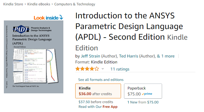
Also, note that we are not getting into how to script with APDL. It is a truly parametric command language in that you can replace most values in commands with parameters. It also has control logic, functions, and other capabilities that you find in most scripting languages. We will focus on the actual commands you use to do things in the program here. If you want to learn more about how to program with APDL, you can purchase a copy of our “Introduction to the ANSYS Parametric Design Language” book. (another plug)
Some APDL Basics
APDL was developed back in the day of punch cards. It was much easier to use than the other programs out there because the commands you entered didn’t have to be formatted in columns. Instead, arguments for commands are separated by commas. Therefore, instead of defining a Node in your model as:
345 12.456 17.4567 0.0034
(note that the location of that decimal point is critical). You create a line as:
N,345,12.456,17.4567, 0.0034
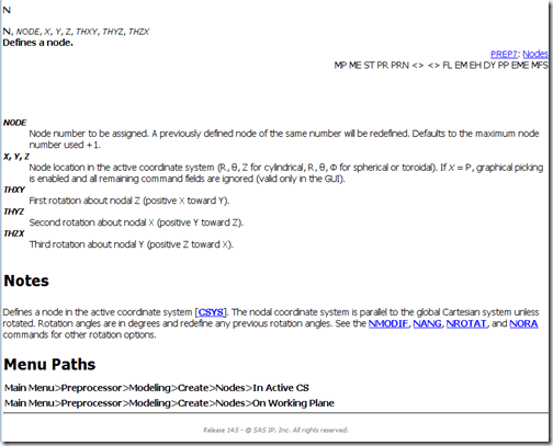
Trust me, that was a big deal. But what you need to know now is that all APDL commands start with a keyword and are followed by arguments. The arguments are explained in the Command Reference in the help. So the entry for creating a node looks like this:
The documentation is very consistent and you will quickly get the hang of how to get what you need out of it. The layout is explained in the help: // Command Reference // 3. Command Dictionary
Another key thing to know about commands in MAPDL is that most entities you create (not loads and boundary conditions) have an ID number. You refer to entities by their ID number. This is a key concept that gets lost if you grew up using GUI’s. So if you want to make a coordinate system and use it, you define an ID for it and then refer to that ID. Same thing goes for element definitions (Element Types), material properties, etc… Remember this, it hangs up a lot of newer users.
To use MAPDL commands, you simply enter each command on a line in a command object that you place in your model tree. We did a seminar on this very subject about two years ago that you can watch here.
The idea of entity selection is fundamental to APDL. Above, we point out that all entities have an ID. You can interact with each entity by specifying its ID. But when you have a lot of them, like nodes and elements, it would be a pain. So APDL deals with this by letting you select entities of a given type and making them “selected” or “unselected” Then, when you execute commands, instead of specifying an ID, you can specify “ALL” and all of the selected entities are used for that command.
Sometimes we refer to entities as being selected, and sometimes we refer to them as “active.” The basic concept is that any entity in ANSYS Mechanical APDL can be one of two states: active/selected or inactive/unselected. inactive/unselected entities are not used by whatever command you might be executing.
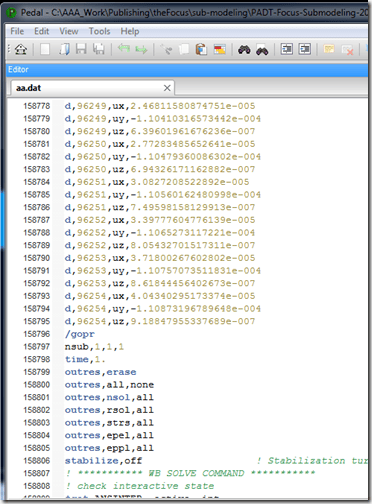
If you want to see all of the APDL commands that ANSYS Mechanical writes out, simply select the setup branch of your model tree and choose Tools->Write Input File. You can view it in a text editor.
One last important note before we go through our list of commands: the old GUI for MAPDL can be used to modify or create models as well as ANSYS Mechanical. Every action you take in the old GUI is converted into a command and stored in the jobname.log file. Many users will carry out the actions they want in an interactive session, then save the commands they need from the log file.
Wait, one more thing: Right now, you need these commands. But at every release, more and more of the solver is exposed in ANSYS Mechanical GUI, and we end up using less and less APDL scripts. So before you write a script, make sure that ANSYS Mechanical can’t already do what you want.
The Commands
1. !
An exclamation point is a comment in APDL. Any characters to the right of one are ignored by the program. Use them often and add great comments to help you and others remember what the heck you were trying to do.
2. /PREP7 – /SOLU – /POST1 – FINISH
The MAPDL program consists of a collection of 10 processors (there were more, but they have been undocumented.) Commands only work in some processors, and most only in one. If you enter in a preprocessor command when you are in the postprocessor, you will get an error.
When you create a command object in your ANSYS Mechanical model, it will be executed in either the Pre processor, the Solution processor, or in the Post processor. Depending on where in the model tree you insert the command object. If you need to go into another processor, you can, you simply issue the proper command to change processors. JUST REMEMBER TO GO BACK TO THE PROCESSOR YOU STARTED IN when you are done with your commands.
/PREP7 – goes to the pre processor. Use this to change elements, create things, or modify your mesh in any way.
/SOLU – goes to the solution processor. Most of the time, you will start there, so you most often will use this command if you went into /PREP7 and need to get back. Modify loads, boundary conditions, and solver settings in this processor.
/POST1 – goes to the post processor. This is where you can play with your results, make your own plots, and do some very sophisticated post-processing.
FINISH – goes to the begin level. You will need to go there if you are going to play with file names.
3. TYPE – MAT – REAL – SECNUM
You only really need to know these commands if you will be making your own elements… but one of those things everyone should know because the assignment of element attributes is fundamental to the way APDL works…. so read on even if you don’t need to make your own elements.
Every element in your model is assigned properties that define the element. When you define an element, instead of specifying all of its properties for each element, you create definitions and give them numbers, then assign the number to each element. The simplest example are material properties. You define a set of material properties, give it a number, then assign that number to all the elements in your model that you want to solve with those properties.
But you do not specify the ID’s when you create the elements. That would be a pain. Instead, you make the ID for each property type “active” and every element you create will be assigned the active ID’s.
The commands are self-explanatory: Type sets the Element Type, MAT sets the material ID, REAL set the real constant number, and SECNUM sets the active section number.
So, if you do the following:
type,4
real,2
mat,34
secnum,112
e,1,2,3,4,11,12,13,14
you get:
ELEM MAT TYP REL ESY SEC NODES
1 34 4 2 0 112 1 2 3 4 11 12 13 14
2 3 4 4 0 200 101 102 103 104 111 112 113 114
4. ET
The MAPDL solver supports hundreds of elements. ANSYS Mechanical picks the best element for whatever simulation you want to do from a general sense. But that may not be the best for your model. In such cases, you can redefine the element definition that ANSYS Mechanical used.
Note: The new element must have the same topology. You can’t change a 4 noded shell into an 8 noded hex. But if the node ordering is the same (the topology) then you can make that change using the ET command.
5. EMODIF
If you define a real constant, element type, or material ID in APDL and you want to change a bunch of elements to those new ID’s, you use EMODIF. This is the fastest way to change an element’s definition.
6. MP – MPDATA – MPTEMP –TB – TBDATA – TBTEMP
Probably the most commonly needed APDL command for ANSYS Mechanical users are the basic material property commands. Linear properties are defined with MP command for a polynomial vs. temperature or MPDATA and MPTEMP for a piece-wise linear temperature response. Nonlinear material properties are defined with the TB, TBDATA, and TBTEMP commands.
It is always a good idea to stick your material definitions in a text file so you 1) have a record of what you used, and 2) can reuse the material model on other simulation jobs.
7. R – RMODIF
If you define an elements formulation with options on the ET command and the material properties on the material commands, where do you specify other stuff like shell thickness, contact parameters, or hourglass stiffness? You put them in real constants. If you are new to the MAPDL solver, the idea of Real constants is a bit hard to get used to.
The official explanation is:
Data required for the calculation of the element matrices and load vectors, but which cannot be determined by other means, are input as real constants. Typical real constants include hourglass stiffness, contact parameters, stranded coil parameters, and plane thicknesses.
It really is a place to put stuff that has no other place. R creates a real constant, and RMODIF can be used to change them.
8. NSEL – ESEL
As mentioned, selection logic is a huge part of how MAPDL works. You never want to work on each object you want to view, change, load, etc… Instead, you want to place entities of a given type into an “active” group and then operate on all “active” entities. (you can group them and give them names as well, see CM-CMSEL-CMDELE below to learn about components)
When accessing MAPDL from ANSYS Mechanical, you are most often working with either nodes or elements. NSEL and ESEL are used to manage what nodes and elements are active. These commands have a lot of options, so review the help.
9. NSLE – ESLN
You often select nodes and then need the elements attached to those nodes. Or you select elements, and you need the nodes on those elements. NSLE and ESLN do that. NSLE selects all of the nodes on the currently active elements and ESLN does the opposite.
10. ALLSEL
A very common mistake for people writing little scripts in APDL for ANSYS Mechanical is they use selection logic to select things that they want to operate on, and then they don’t remember to reselect all the nodes and elements. If you issue an NSEL and get, say the nodes on the top of your part that you want to apply a load to. If you just stop there, the solver will generate errors because those will be the only active nodes in the model.
ALLSEL fixes this. It simply makes everything active. It is a good idea to just stick it at the end of your scripts if you do any selecting.
11. CM – CMSEL
If you use ANSYS Mechanical, you should be very familiar with the concept of Named Selections. These are groups of entities (nodes, elements, surfaces, edges, vertices) that you have put into a group so you can scope based on them rather than selecting each time. In ANSYS MAPDL, these are called components, and commands that work with them start with CM.
Any named selection you create for geometry in ANSYS Mechanical gets turned into a nodal component – all of the nodes that touch the geometry in the Named Selection get thrown into the component. You can also create your own node or element Named Selections, and those also get created as components in MAPDL.
You can use CM to create your own components in your APDL scripts. You give it a name and operate away. You can also select components with the CMSEL command.
12. *GET
This is the single most awesomely useful command in APDL. It is a way to interrogate your model to find out all sorts of useful information: number of nodes, largest Z value for node position, if a node is selected, loads on a node, result information, etc…
Check out the help on the command. If you ever find yourself writing a script and going, “if I only knew blah de blah blah about my model…” then you probably need to use *get.
13. CSYS – LOCAL – RSYS
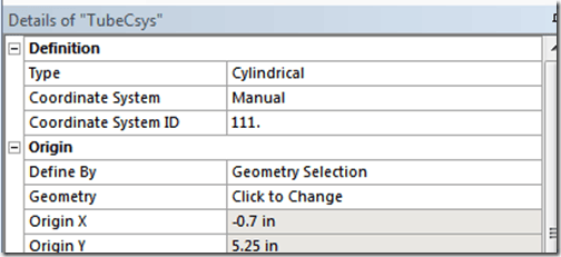
Coordinate systems are very important in ANSYS Mechanical and ANSYS MAPDL. In most cases, you should create any coordinate systems you need in ANSYS Mechanical. They will be available to you in ANSYS MAPDL, but by default, ANSYS Mechanical assigns a default ID. To use a coordinate system in MAPDL you should specify the coordinate system number in the details for a given coordinate system by changing “Coordinate System” from “Program Defined” to “Manual” and then specifying a number for “Coordinate System ID”
If you need to make a coordinate system in your APDL script, use the LOCAL command.
When you want to use a coordinate system, use CSYS to make a given coordinate system active.
Note: Coordinate system 0 is the global Cartesian system. If you change the active coordinate system, make sure you set it back to the global system with CSYS,0
RSYS is like CSYS but for results. If you want to plot or list result information in a coordinate system other than the global Cartesian, use RSYS to make the coordinate system you want active.
14: NROTATE
One thing to be very aware of is that each node in a model has a rotation associated with it. By default, the UX, UY, and UZ degrees of freedom are oriented with the global Cartesian coordinate system. In ANSYS Mechanical, when you specify a load or a boundary condition as normal or tangent to a surface, the program actually rotates all of those nodes, so a degree of freedom is normal to that surface.
If you need to do that yourself because you want to apply a load or boundary condition in a certain direction besides the global Cartesian, use NROTATE. You basically select the nodes you want to rotate, specify the active coordinate system with CSYS, then issue NROTATE,ALL to rotate them.
Be careful, though. You don’t want to screw with any rotations that ANSYS Mechanical specified.
15. D
The most common boundary condition is displacement, even for temperature. To specify those in an ANSYS MAPDL script, use the D command. Most people use nodal selection or components to apply displacements to multiple nodes.
In its simplest form, you apply a single value for displacement to one node in one degree of freedom. But you can specify multiple nodes, multiple degrees of freedom, and more powerfully, the value for deflection can be a table. Learn about tables here.
16. F
The F command is the same as the D command, except it defines forces instead of displacement. Know, it, use it.
17. SF – SFE
If you need to apply a pressure load, you use either SF to apply to nodes or SFE to apply to elements. It works a lot like the D and F commands.
18. /OUTPUT
When the ANSYS MAPDL solver is solving away, it writes bits and pieces of information to a file called jobename.out, where jobname is the name of your solver job. Sometimes you may want to write out specific information, say list the stresses for all the currently selected nodes, to a file. use /OUTPUT,filename to redirect output to a file. When you are done, specify /OUTPUT with no options, and it will go back to the standard output.
19. /SHOW
ANSYS MAPDL has some very sophisticated plotting capabilities. There are a ton of commands and options used to set up and create a plot, but the most important is /SHOW,png. This tells ANSYS MAPDL that all plots from now on will be written in PNG format to a file. Read all about how to use this command, and how to control your plots, here.
20. ETABLE
The ANSYS MAPDL solver solves for a lot of values. The more complex the element you are using, the more the number of values you can store. But how do you get access to the more obscure ones? ETABLE. Issue 38 of The Focus from 2005 goes into some of the things you can do with ETABLE.
Where to go From Here
This is certainly not the definitive list. Ask 20 ANSYS MAPDL users what APDL commands all ANSYS Mechanical users should know, and you might get five or six in common. But based on the support calls we get and the scripts we write, these 20 are the most common that we use.
Command help is your friend here. Use it a lot.
The other thing you should do is open up ANSYS MAPDL interactively and play with these commands. See what happens when you execute them.
Also, if you are interested in how APDL came about, please listen to our interview with the founder of the company that became Ansys, the primary author of the solver in Ansys Mechanical APDL, and the man who created these APDL commands – John Swanson. None of this content and PADT itself would not exist without the vision he had.
Learn more about APDL commands with PADT’s definitive guide: Introduction to the ANSYS Parametric Design Language

