Many Flownex users are familiar with using the Designer to size components to meet design requirements or using parameter tables to sweep through various operating conditions. Well, what if you need to do both? You may want to know operational inputs (without building out controls) for various operating conditions. Flownex currently offers component level (“Change Design”), precompiled steady state controller scripts, or running the designer through a script. Flownex version 8.15.0 now allows users to run the Designer during a Parameter Table run through the GUI.
Introduction
Today we will walk through how to embed a designer setup inside of a Parameter Table to vary the oil inlet pressure into a gearbox cooling compartment. We will use the designer to adjust the opening of the air bleed opening, to ensure that our container interface (top/bottom) maintains force balance across an oil lubrication system at each design point.
Network Description
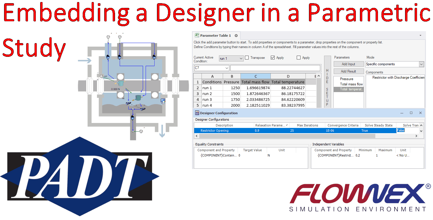
For our network, we will be modelling a simplified turbine lubrication system. Air is introduced through labyrinth seals, modelled as a boundary condition, and exits through a restriction at the top of the compartment. Oil is introduced to the container and partially entrained with air (through a simple fixed percentage) before exiting the compartment. Below is a diagram of the system.

The container interface top/bottom components allow us to specify the steady state level of oil in the bearing compartment. We will need to enforce force balance across the air/oil interface to ensure that oil will not be flooding or purging. In this network, we have used the designer to balance interfacial forces by adjusting the area of the outlet air restriction.
Designer Setup
We will look at how the temperature of the compartment varies with oil inlet pressure. However, we will need to vary the pressure drop of the air outlet to maintain force balance across the air/oil interface for each inlet pressure scenario. Rather than model air outlet pressure regulation, we will use the Designer to set the opening of the restrictor to achieve force balance.

Parameter Table Setup
After creating a Designer setup to maintain force balance, we can create our Parameter Table (covered in a previous post). Our parametric study will vary the oil inlet pressures and log the resultant mass flow rate and temperature of the oil air mixture exiting the system.

Nested Parametric Study
Once we have created our parameter table and Designer setup, we can run a parametric study by clicking “Run Parameter Table” from the Home Menu. The parametric study will require us to choose a Parameter Table, then select additional run configuration options. We will select our Designer name from the dropdown and leave all of the other options as default, then select “OK”.

With a few clicks we have nested our Designer inside of the parametric study – no scripts required.