
Note: If you know PyAnsys and just want the script, skip to the bottom of this post.
Welcome to the final entry for how to use PyAnsys to create a program that reads results from Ansys Mechanical and Ansys Mechanical APDL and converts them to a variety of 3D File Formats, including a file that allows you to 3D Print your Ansys results. The goal of these posts is to provide an advanced tutorial for people learning PyAnsys and for people who need this type of a tool.
If you landed on this post first, here is a summary of where we are:
In Part 1 of this series, we covered:
- How to install and set up PyAnsys on your machine
- Create a PyAnsys script that reads an Ansys Mechanical result file
- Pull mesh and results from the file
- Plot results to the screen using Python
- Write a VTK file of the results
In Part 2, we covered:
- Parameterize things
- Support multiple result types
- Distort the mesh
- Write a WRL/VRML file we can use for 3D Printing
If you have not used PyAnsys before, please go and review the first half of the Part 1 to learn how to get PyAnsys working for you. You can certainly use the script included in the post as a black box, but if you want to get a feel for what is going on, please read both previous parts. Also, some users have had issues with out-of-date modules. Doing the full install as shown in the first article will make sure you have the latest and greatest.
Time to Take PyAnsys to the Next Level and Add a GUI and More File Formats
The previous version of the code works, expecially if you are converting from Ansys results to something you can 3D Print every once in a while. The variables are hard coded into the script and you just need to update them for a new result set.
But that is not very flexible not a piece of code that my High School math teacher who taught me Basic in 1981 would be proud of. So To make it a more useful tool we need to add a Graphical User Interface (GUI), some error checking, and add some other file formats.
As in the previous posts, we break the code up into sections to explain each one. Most of the information is in the comments. Do note that the full script is in a Zip file at the end of the post.
1: Get All the Modules Loaded and a Bit About TKInter
As with any aspect of Python, there are many choices for what to use for a GUI. I picked TKInter for not other reason than I used to be a fairly good Tcl/TK programer back when Ansys used it for the Mechanical APDL and Ansys ICEM-CFD GUI’s. It was the best multi-operating system GUI for engineering software… in 2002. Once I commited to using it I learned there really was not much knowledge that was transferable, but it worked and I stuck with it.
What gets funky about this module is how you locate things in a window. I decided to use the Row and Column pack so things don’t move around when you resize a window. You will see that in the code when we put the widgets in the window.
You can learn about TKInter in the Python.org documentation: https://docs.python.org/3/library/tkinter.html
The other modules are the same as in the Part 2 version of the script:
#### SECTION 1 ####

#1.1: Get all modules loaded, starting with the Ansys realted ones
from ansys.dpf import post
from ansys.dpf import core as dpf
from ansys.dpf.core import operators as coreops
from ansys.dpf.core import fields_container_factory
from ansys.dpf.core.plotter import DpfPlotter

#1.2: For our GUI, we will us TKInter
#     So load what we are going to use for TKInter
#     https://docs.python.org/3/library/tkinter.html
import tkinter as tk
from tkinter import *
from tkinter import ttk
from tkinter import filedialog as fd
from tkinter.messagebox import showerror
from tkinter import scrolledtext

#1.3: Now we need pyvista, numpy and os to output in some formats
#       pyansys doesn't support, play with the data, and interact with
# #     the operating system.
import pyvista as pv
import numpy as np
import os

# Jump down to the main program for section 2!
#  This program is now big enough to have fundtions.
2: Building the GUI with Python TKInter
OK, buckle in, this gets a bit long. Most of what you need to know is in the comments.
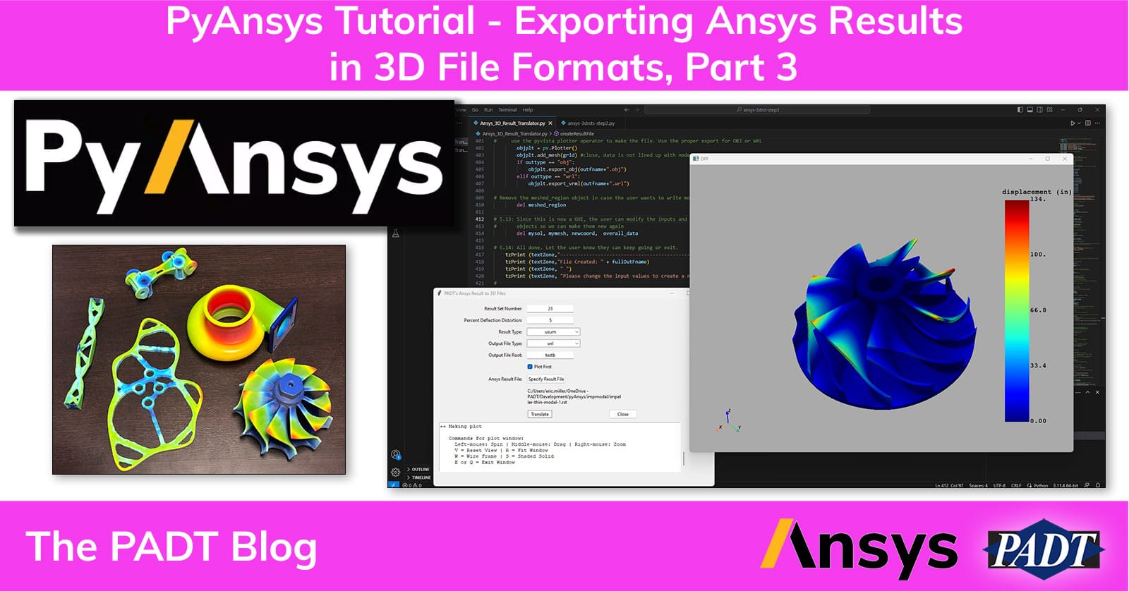
Here is what the window looks like when it first pops up:

Before we get to the script, let’s take a look at the window when we have filled it out and add numbers for each of the widgets we need to create, then we will talk a bit about each one.

GUI Obtects:
- The Window (myDialog)
TKInter refers to this as the “Dialog” You give a size, a title, and some other info. I went simple, but you can be fancy in how you want your window to look
Not shown in the window, is the Frame (frm1). That is the object that holds your GUI widgets. - Text Input: Result Set Number (rstNum)
Row 1, Column 2 and 3
This consistes of a text label “Result Set Number:” in Column 2 and text input in Column 3.
Because we have multiple text inputs, we use a function, bldInput() to create each of them. - Text Input: Precent Develetion Distortion (pcntdfl)
Row 2, Column 2 and 3 - Drop Down: Result Type (rsttype)
Row 3, Column 2 and 3
We want to let the user pick which of the result types they want to extract from the result file, so we load them into a list and then use a funciton, bldDrop() to create the widget with the label.
If you need to add a new result type, add it to the list.
(‘u’,’ux’,’uy’,’uz’,’usum’,’sx’,’sy’,’sz’,’s1′,’s2′,’s3′,’seqv’,’tmp’) - Drop Down: Output File Type (outtype)
Row 4, Column 2 and 3
Same here, make a list and feed the list and lable to bldDrop() what output format do they want. If ou want to support a new format, add it to the list.
(‘vtk’,’obj’,’stl’,’wrl’,’none’) - Text Input: Output File Root (outRoot)
Row 5, Column 2 and 3
This is a bit lazy, we should have them chose a filename after the script runs to save the results, but I’m lazy. The script uses this name with the file type appeneded to create the output file in the same directory as the input file. A great addition would be to add a button to define the output directory. This uses bldInput() as well. - Check Box: Plot First (doPlot)
Row 6, Column 3.
The decision to plot the result before you make the file is a yes/no questino, so use a check box to turn that option on and off. Only one so we use the TKInter functions ttk.Checkbutton() to make it.
This is our first use of a TKInter function to make a widget. YOu can see that you put the frame where you want it, a label, and the variable to define (doPlot). Then you use .grid to specify the row and column as well as the allignment (sticky). - Button: (open_button)
Row 7, Column 2 and 3
To specify the input file, we want to use the TKInter function, filedialog.askopenfilename(). As you will see, we do that with a seperate function that is called by a button. First you make a label then the button. As you can see, the button points to the “select_file” funtion we discuss in Section 3. - Label (filename_lbl)
Row 8, Column 3 through 4
We want to show what file the user picked, so we create a blank label for that. It doesn’t need a label in Column 2. But it does span Column 3 and 4. - Button (doTranslate)
Row 9, Column 3
We are finaly to the part where the user can stop specifying things and run the script. We use a button, with a label of Translate, that calls doTranslate() when it is clicked. More in Section 3. - Button (closeIt)
Row 9, Column 4
We also need a more elegant way to exit than closing the window, so we add a Close button. It calls closeIt() when clicked. More in Section 3. - Scrolled Text: (textZone)
Row 10, Column 2 through 5
We want to give feedback to the user. The proper way to do that would be with opening dialog boxes when we needed to share something, but that is a lot of work. So instead, we careat a text widget and write to it as if we were printing to the command line. We give it a width of 80 characters and a height of 8 lines. Note that it starts in Column 1 and spans 4 columns.
This is a very basic user interface, and we are using basic widgets. But you can see it’s not hard to through something a fellow engineer would use. I’d go with a more sophisticated GUI option if you were going to write something for the masses.
One word on the last line in this section, “myDialog.mainloop().” If you have done GUI programming before you know this kicks of the Event Loop. Bascially, in an event loop, the program puts the window up and then waits for the user to interact with the window. It handles most things behind the scene, like typing in text inputs or clicking check boxes. Control doesn’t come back to your program until someone clicks on a button that has one of your functions attached to it. And, when your function is done running, control returns to the event loop.
Here is the actual code that does what we just saw and talked about:
#  ##### SECTION 2 #####
#
# Start the program by putting a window up for the user to enter info in
#     Since we have a GUI, the main program simply builds and launches the GUI
#     Then the actual actions to view and write results out happen when the
#     User presses the "translate" button

#2.1: We use a call to TK to open a window (dialog) and we give it some
#       parameters to make it look like we want.
#       NOTE: TK uses this row column format to place items

myDialog = Tk()
myDialog.title("PADT's Ansys Result to 3D Files")
myDialog.geometry('750x500')
myDialog.columnconfigure(0, weight=1)
myDialog.rowconfigure(0, weight=1)

#2.2: The widgets go into a frame, so make that.
#     frm1 is a global variable and we will us it to back the window with
#     our various input widgets
frm1 = ttk.Frame(myDialog, padding="10 10 10 10")
frm1.grid(column=0, row=0, sticky=(N, W, E, S))

#2.3: To keep things cleaner, we use a function called bldInput() (Section 3)
#     to create text input widgets.
#     Feed it the variable we want the input to go into, the text we want
#     for the lable, and what row number we want to place it in.
#     Build input for the result set number and % deflection.
rstNum = StringVar()
bldInput(rstNum,"Result Set Number:",1)

pcntdfl = StringVar()
bldInput(pcntdfl,"Percent Deflection Distortion:",2)

# 2.4: Now we need a drop down
#      Again, we are going to use a function, bldDrop()
#      It takes the variable to fill, the lable text, a list of strings,
#      and the row number
#      To allign you use "sticky" with N, S, E, W
#      to specify where in the cell to allign
#      Build a dropdown for the result type and the output format
rsttype = StringVar()
rsttype_list = ('u','ux','uy','uz','usum','sx','sy','sz','s1','s2','s3','seqv','tmp')
bldDrop(rsttype,"Result Type:",rsttype_list,3)

outtype = StringVar()
outtype_list = ('vtk','obj','stl','wrl','none')
bldDrop(outtype,"Output File Type:",outtype_list,4)

#2.5: Use bldInput() to create a text input widget for the output file root
outroot = StringVar()
bldInput(outroot,"Output File Root:",5)

# 2.6: We only have one checkbox, so no need for a function
#      Just build it and put it in row 6
#      Set the variable, doPlot to 1 so the default is "yes"
doPlot = IntVar(value=1)
doPlotChk = ttk.Checkbutton(frm1, text = "Plot First", variable=doPlot )
doPlotChk.grid(column=3, row=6, sticky=W)

# 2.7: To specify the result file, we are going to open up a
#      file dialog and let the user define the file.
#      This gets a bit fancy

# 2.7.1: Get the label on there in column 2, row 7
ll = ttk.Label(frm1, text="Ansys Result File:").grid(column=2, row=7,sticky=E)

# 2.7.2: Now make a button that executes the "select_file" command
open_button = ttk.Button(frm1, text='Specify Result File', command=select_file)
open_button.grid(column=3, row=7, sticky=W)

# 2.7.3: Once the user does pick a file, we want to show their
#        choice, so make a text label and leave it blank
rstFile = StringVar()
filename_lbl = ttk.Label(frm1, text="   ",wraplength=250)
filename_lbl.grid(column=3, row=8, sticky=W, columnspan=2)
#------

#2.8: Now we need the two OK/Cancel buttons, but we will use "translate" and "close"
#     Very simple, they got to two functions, doTranslate and closeIt
ttk.Button(frm1, width=-10, text="Translate", command=doTranslate).grid(column=3, row=9, sticky=W)
ttk.Button(frm1, text="Close", command=closeIt).grid(column=4, row=9, sticky=W)

#2.9: We want to give some feedback to the user as we run
#     This is old school, but we are going to make a
#     scrolled text region and print out messages
#     to that widget like we would to the command line.
#     we will use a function, tzPrint() to output to this zone
textZone = scrolledtext.ScrolledText(frm1,width = 80, height = 8)
textZone.grid(column=2,row=10, columnspan=4, pady=10, padx = 10)


#2.10: To make everything not look so crowded, add 5px of
#      padding to every widget we just made.
for child in frm1.winfo_children():
    child.grid_configure(padx=5, pady=5)

#2.11: If the user presses return, then do the translation
myDialog.bind("<Return>", doTranslate)

#2.12: Use tzPrint to output our first messages.
tzPrint(textZone,"+++ Initialized +++")
tzPrint(textZone,"Please fill out every field")

#2.13: Finaly!  We are ready to go, launch the window and wait for input from the user.
myDialog.mainloop()
3. Graphical Interface Functions
To make things cleaner, we moved some repeated code into functions and we need to have functions that get called when the user clicks on a button. This section has both. The only function missing is doTranslate() which calles createResultFile(), which we cover in Sections 4 and 5.
The comments are pretty detailed and should explain most things. Take a look at the TKInter documentation is you need more explination.
#  ##### SECTION 3 #####
#
# Graphical Interface funtions
#
# These functions are used to simplify the creation and update of GUI items.
#     They use global frm1 = the frame the gui is in
#
# 3.1: Make a text input
#       Takes the variable that is being entered, a text label,
#       and what row it goes into
#       The widget is put on the specified row,
#       the label is in column 2 and the input in column 3
#       The label is right justfied (E) and the input is left justified (W)
def bldInput(theVar,theLbl,theRow):
    ttk.Label(frm1, text=theLbl).grid(column=2, row=theRow, sticky=E)
    theEntry = ttk.Entry(frm1,  textvariable=theVar, justify=CENTER)
    theEntry.grid(column=3, row=theRow,  sticky=W)

# 3.2: Make a dropdown input widget
#      This also uses frm1 and takes the variable, a lable, and row number as inpu
#      Most importantly, it also takes a python list full of the
#       items to put in the drop down. that goes in as 'values'
#       The widget is put on the specified row,
#       the label is in column 2 and the input in column 3
#       The label is right justfied (E) and the input is left justified (W)
def bldDrop(theVar,theLbl,theList,theRow):
    ttk.Label(frm1, text=theLbl).grid(column=2, row=theRow, sticky=E)
    theDrop = ttk.Combobox(frm1,textvariable=theVar,state="readonly", justify=CENTER)
    theDrop['values'] = theList
    theDrop.grid(column=3, row=theRow, sticky=W)

#3.3: To give input to the users, we want to print to the text zone called tz.
#     This requires unlocking the zone, adding the text,
#     scrolling to the bottom, locking the zone, then updating the window
def tzPrint(tz,val):
    tz.configure(state ='normal')
    tz.insert(tk.INSERT,val+"\n")
    tz.see(tk.END)
    tz.configure(state ='disabled')
    myDialog.update()

#3.4: This is a simple function that we use to close down the window
#      when the user presses the "close" button
def closeIt():
    myDialog.destroy()

#3.5: This is the function that gets called when they
#     click on "choose result file" It is a standard dialog
#     It uses the TKInter filedialog to let he user specify the result file
#     Key is specifying the two types of Ansys mechanical result files.
#     It is pretty simple, you specify a list of filetypes,
#     then call the askopenfilename() function and feed it a title,
#     starting directory, and the filetype list.
#     Once the user is done, the askopenfilename() returns the filename
#     Then we put that value in the blank label we created before. (filename_lbl)
def select_file():
    global rstFile
    filetypes = (
        ('Structural Result files', '*.rst'),
        ('Thermal Result files', '*.rth'),
        ('All files', '*.*')
    )

    rstFile = fd.askopenfilename(
        title='Open a file',
        initialdir='/',
        filetypes=filetypes)
    filename_lbl.configure(text=rstFile)
4: Start the Translation Process with some Variable Grabbing and Error Checking
One the user hits the “Translate” button doTranslate() gets called. Now, being lazy, I’d rather just have thigns crash if variables are wrong or missing, but we should be responsible and check the inputs to make sure they make sense and none are missing. We don’t get to fancy on this.
Each check is explained in the comments. Our goal here is to get the variables and then pass them to createResultFile(rn,pd,rt,rf,rd,ot,or1,dp). If we do run into an error, we display it in an error popup dialog and let the user try again.
#   ##### SECTION 4 #####
#
# The doTranslate() funtion gets executed when the user presses "Translate"
# Mostly error checking, the calls createResultFile if all is good,
# or shows errors if not
#
# 4.1: This comes after the user pushes the "translate" button,
#      so we want to check all the variables we need
#      Set up a list, missingVals so we can keep track of what is not there
#      Go through each variable and make sure it is not blank.
#      We can do that for values that are not a string by using the
#      try/except python construct. But a blank string is
#      not an error so for strings we just need to check their length.
#
#      You use get() to pull the value from each widget.
#
def doTranslate(*args):
    missingVals = []

### reselt set number is an int, so try and pull it and use except if it is missing
    try:
        rn = int(rstNum.get())
    except:
        missingVals.append("Result Set Number")

### precent deflection is a float, so try and cast it to float and
#   except if it is missing
    try:
        pd = float(pcntdfl.get())
    except:
        missingVals.append("Percent Deflection Distortion")

### Result type is a strong, so pull it then check the length.
#   If it is zero, add an missing message
    rt = rsttype.get()
    if len(rt) == 0:
        missingVals.append("Result Type")
###
###  We get two things here, the directory (rd) and the filename.
#    We are using the path tool so
#    the except works for a missing filename
    try:
        chk = len(rstFile)
        rf = os.path.basename(rstFile)
        rd = os.path.dirname(rstFile)
    except:
        missingVals.append("Result File")

### Another string, check length
    ot = outtype.get()
    if len(ot) == 0:
        missingVals.append("Output File Type")

### Another string, check length
    or1 = outroot.get()
    if or1 == 0:
        missingVals.append("Output File Root")

# nothign to check for the plot checkbox, so just pull the value
    dp = doPlot.get()
##
# 4.2: We have checked everything, now see if anything was missing.
#      Do this by looking at the lenght of the missing list,
#      If the length is zero, all is good and pass the extracted
#      values to createResultFile()
#      If there was a problem, use the TKInter showerror()
#      tool to list all the missing values in a message
#      and return to the window
    if len(missingVals) == 0:
        createResultFile(rn,pd,rt,rf,rd,ot,or1,dp)
    else:
        showerror(title="Missing Input, please specify a value for each input!", message = "\n".join(missingVals))
#
#end doTranslate()
5. Time to Read and Translate the Ansys Results
As you an see, adding a GUI adds a lot to a script. But your users will appreciate it. Now that we have everything ready to run, we can actually do the work of creating a new 3D result file with the createResultFile() function. Pretty much everythign in this routine is what was in the script from Part 2. Here is what is different:
- We don’t hard code the variable values, they get passed into the createResultFile() function.
- Instead of printing to the console, we use the tzPrint() function to pass information to the user in the scrolling text zone in the window.
- To help the user out, if they want to see a plot of the results, we put the keyboard commands and mouse mappings for the PyVista graphics window in the text scroll zone.
- We added some file formats:
- STL: This is just a distorted mesh, there is no color information in STL files
- OBJ: This uses the same calls as WRL, so might as well include it.
- Since the user returns to the window to make more files, we need to clean up the data we created, so there are some “del” commands at the end of this funtion.
#  ##### SECTION 5 #####
#
#  This is the actual workhourse function.
#   We have all the information from the user, now we need to
#   get results, calcs distortion, displays a plot,
#   and makes the requested 3D output file.
#   This is bascially the script from the Part 2 tutorial with some additions
#
def createResultFile(rstnum,pcntdfl,rsttype,rstFile,rstDir,outtype,outroot,doPlot):

# 5.1: Build the output file name from the file root and
#      the result type and file type
    outfname = outroot + "-" + rsttype + "-" + str(rstnum)
    fullOutFname = rstDir+outfname+"."+outtype

# 5.2: Set a boolean on blotting. We want "true or false"
#       for the message to the user
    if doPlot ==1:
        doplot = TRUE
    else:
        doplot = FALSE

# 5.4: Let the user know what the parameters are by putting a
#      message in the textZone.
    tzPrint (textZone,"===========================================================================")
    tzPrint (textZone,"Starting the translation of your Ansys results to a different file format")
    tzPrint (textZone,"  Input file: "+rstFile)
    tzPrint (textZone,"  Solution Step/mode: "+str(rstnum))
    tzPrint (textZone,"  Result type: "+rsttype)
    tzPrint (textZone,"  Percent deflection distortion: "+str(pcntdfl))
    tzPrint (textZone,"  Output file: "+outfname+"."+outtype)
    tzPrint (textZone,"  Plot before making file: "+str(doplot))
    tzPrint (textZone,"---------------------------------------------------------------------------")

#5.5: Open the result file and load the solution and mesh
    path1 = os.getcwd()
    os.chdir(rstDir)
    path = os.getcwd()
    mysol = post.load_solution(rstFile)
    mymesh = mysol.mesh

#5.6: Grab the results from the specified solution step,
#     then get the request result type (thermal or displacement and stress)

    tzPrint (textZone,"++ Getting result information from file")

# displacement, stress, and thermal for the solution set number
    if rsttype == "tmp":
        thrm1 = mysol.temperature(set=rstnum)
    else:
        dsp1 = mysol.displacement(set=rstnum)
        str1 = mysol.stress(set=rstnum)

#5.7: Use an if statement to pull in the specific result values
#     Add in a try/except to catch when they put in a
#     result type or number that is not in the file
# Start with displacement
    try:
        if rsttype == "u":
            rstval = dsp1.vector.result_fields_container
        elif rsttype == "ux":
            rstval = dsp1.x.result_fields_container
        elif rsttype == "uy":
            rstval = dsp1.y.result_fields_container
        elif rsttype == "uz":
            rstval = dsp1.z.result_fields_container
        elif rsttype == "usum":
            rstval = dsp1.norm.result_fields_container

# Now check for stresses
        elif rsttype == "seqv":
            rstval = str1.von_mises.result_fields_container
        elif rsttype == "s1":
            rstval = str1.principal_1.result_fields_container
        elif rsttype == "s2":
            rstval = str1.principal_2.result_fields_container
        elif rsttype == "s3":
            rstval = str1.principal_3.result_fields_container
        elif rsttype == "sx":
            rstval = str1.xx.result_fields_container
        elif rsttype == "sy":
            rstval = str1.yy.result_fields_container
        elif rsttype == "sz":
            rstval = str1.zz.result_fields_container
        elif rsttype == "xy":
            rstval = str1.xy.result_fields_container
        elif rsttype == "xz":
            rstval = str1.xz.result_fields_container
        elif rsttype == "yz":
            rstval = str1.yz.result_fields_container

# Last, do temperatures
        elif rsttype == "tmp":
            rstval = thrm1.scalar.result_fields_container
    except:
        tzPrint (textZone,"###################################################################")
        tzPrint (textZone,"    ERROR")
        tzPrint (textZone,"Could not find the result you are looking for on the result file")
        tzPrint (textZone,"   Change the requested result type, number, or the file")
        tzPrint (textZone,"###################################################################")
        return FALSE
# 5.8: If this is thermal, just copy the
#      undistored mesh to the variables we will us to plot and write
    if rsttype == "tmp":
        dflmesh = mymesh.deep_copy()
        newcoord = dflmesh.nodes.coordinates_field
    else:
#5.9: Not thermal so get info needed to calculate a distorted mesh
        tzPrint (textZone,"++ Calculating deflection distortion")
# Calcluate the distortion amounts
# Grab the total distortion at each node
        usumval = dsp1.vector.result_fields_container

# Get model extents. Feed the min_max operator "mymesh"
        extop = dpf.operators.min_max.min_max(mymesh.nodes.coordinates_field)
        coordmin = extop.outputs.field_min()
        coordmax = extop.outputs.field_max()

# Look at the X, Y, Z min and max coordinate
#   value and find the biggest demention of the mesh
#   There is probably a clever python way to do this in one line
        dltmax =0.0
        for i in range(0,3):
            if (coordmax.data[i]-coordmin.data[i]) > dltmax:
                dltmax = coordmax.data[i]-coordmin.data[i]

# Get the maximum deflection value from usumval
        umaxop = dpf.operators.min_max.min_max(field=usumval)
        umax = 0.0
        for i in range(0,3):
            if (umaxop.outputs.field_max().data[i]) > umax:
                umax = umaxop.outputs.field_max().data[i]

# Calculate a scale factor that is the specified
#   percentage of the max deflection devided by the max size
        dflsf = pcntdfl/100.0
        sclfact = dflsf*dltmax/umax

#5.10: Scale the deflection values then distort the nodal coordinates

# Get a copy of the mesh to distort
        dflmesh = mymesh.deep_copy()
        newcoord = dflmesh.nodes.coordinates_field

# Scale the deflection field by the scale factor
        sclop = dpf.operators.math.scale(usumval,float(sclfact))
        scaledusum = sclop.outputs.field()


# Add the scaled deflection field to the nodal positions
        addop = dpf.operators.math.add(newcoord, scaledusum)
        tempcoord = addop.outputs.field()

# Overwrite the nodal positions of dflmesh with the deflected ones
        newcoord.data = tempcoord.data

# 5.11: No addition from the part 2 vesrion, we check
#       the doplot flag to see if the user wants a plot or not
#       if they do, let them know, make a DPFPlotter object, then build the plot up
    if doplot:
        tzPrint (textZone,"++ Making plot")
        tzPrint (textZone,"   ")
        tzPrint (textZone,"   Commands for plot window:   ")
        tzPrint (textZone,"     Left-mouse: Spin | Middle-mouse: Drag | Right-mouse: Zoom")
        tzPrint (textZone,"     V = Reset View | R = Fit Window")
        tzPrint (textZone,"     W = Wire Frame | S = Shaded Solid")
        tzPrint (textZone,"     E or Q = Exit Window")

        plt = DpfPlotter()
        plt.add_field(rstval[0],dflmesh,show_edges=False)

#display the plot
        plt.show_figure(
            show_axes=True,
            parallel_projection=False,
            background="#aaaaaa"
        )
# 5.12:  This is where we create teh various formats.
#        For this version we will add OBJ and STL as options.

    tzPrint (textZone,"++ Making output file")

# 5.12.1: No change from previous version for the VTK format
    if outtype == "vtk":
        vtkop = coreops.serialization.vtk_export()
        vtkop.inputs.mesh.connect(dflmesh)

        vtkop.inputs.file_path.connect(outfname+".vtk")
        vtkop.inputs.fields1.connect(rstval)

        vv = vtkop.run()

# 5.12.2: Pyansys includes an STL output capability, so me might as well use it
#         NOTE: STL does not support colors, so this is just a distorted faced file.
    elif outtype == "stl":
        stlop = coreops.mesh.stl_export()
        stlop.inputs.mesh.connect(dflmesh)
        stlop.inputs.file_path.connect(outfname+".stl")

        stlop.run()

#5.12.3: OBJ and WRL need to use teh pyVista modules to write a file.
#        Many of the steps are the same so we start by
#     The pyvista module does not work with the Ansys mesh object,
#     so you have to do some fancy converstion to get the mesh into a
#     grid it can use
#     It also doesn't automatically handle element values vs nodal value,
#     so we have to handle that
#     We set things up the same for OBJ and WRL,
#     then use different functions to do the actual export
    elif outtype == "obj" or outtype == "wrl":

# Get the result field and the deflected mesh into some variables.
        field = rstval[0]
        meshed_region = dflmesh

# We are going to need the name of the field in "field"
# in order to grab it later
        fieldName = '_'.join(field.name.split("_")[:-1])

# Look in the field to see if the location of the results is nodal or elemental
        location = field.location
        if location == dpf.locations.nodal:
            mesh_location = meshed_region.nodes
        elif location == dpf.locations.elemental:
            mesh_location = meshed_region.elements
        else:
            raise ValueError(
                "Only elemental or nodal location are supported for plotting."
            )

# Next we are going to use a mask to get a grid them assign resutls to
# either the element or nodal data
        overall_data = np.full(len(mesh_location), np.nan)
        ind, mask = mesh_location.map_scoping(field.scoping)
        overall_data[ind] = field.data[mask]
        grid = meshed_region.grid
        if location == dpf.locations.nodal:
            grid.point_data[fieldName] = overall_data
        elif location == dpf.locations.elemental:
            grid.cell_data[fieldName] = overall_data

# Now that we have a grid and values on the grid,
#     use the pyvista plotter operator to make the file.
#     Use the proper export for OBJ or WRL
        objplt = pv.Plotter()
        objplt.add_mesh(grid) #close, data is not lined up with nodes
        if outtype == "obj":
            objplt.export_obj(outfname+".obj")
        elif outtype == "wrl":
            objplt.export_vrml(outfname+".wrl")

# Remove the meshed_region object in case the user wants to write more files
        del meshed_region

# 5.13: Since this is now a GUI, the user
#       can modify the inputs and make more files, so we need to remove
#       objects so we can make them new again
        del mysol, mymesh, newcoord,  overall_data

# 5.14: All done. Let the user know they can keep going or exit.
    tzPrint (textZone,"---------------------------------------------------------------------------")
    tzPrint (textZone,"File Created: " + fullOutFname)
    tzPrint (textZone, " ")
    tzPrint (textZone, "Please change the input values to create a new file or if you are finished, click Close")
#
# End of createResultFile()
A Long and Winding PyAnsys Road, But We Got There
Well that was fun. I learned a ton and I’m hoping those of you who have been reading along, or are reading this long after, learned as well. PyAnsys is still young and I suspect there will be a lot more comming down the road for us to leverage to make ourselves and other users more efficient and make our simulation processes more powerful. Others here at PADT have jumped in and we hope to publish more on this topic.
Here is a zip file with the final, full PyAnsys script along with my input files and some output files.
NOTE: Some users have let us know that you need to make sure all your python modules are up-to-date, especially numpy.py. To do this, install the core Ansys modules and pyvista and everything should get updated:
py -m ensurepip --upgrade
py -m pip install ansys-dpf-core
py -m pip install ansys-dpf-post
py -m pip install pyvista
And here is the official link to the tool in GitHub:

There is a lot more we could add to this tool, but if you look at things it is pretty much 80% of what people need, and it would be a lot more work to add that 20%. Some features on the to-do list are:
- Handle units better. You could grab the units from the Ansys result file and then let the use specify mm or inches and do the translation.
- Put in a “Save” call so the user can specify the output directory and filename after the file is prepped and just before the actual save command is run.
- Add other file formats, expecially 3MF. I could not find any ready-to-go python libraries for 3MF so I didn’t add that.
- Read more from the result file and give the user better options based on what is in the file.
- More information on the plot window.
This code is offered up free for anyone to use and modify. So if you want to add any of these features, or one you want, please just share the result back here. I’ll update this post and give full credit where due.
If this stuff gets you interested in doing more automation with PyAnsys scripting, but you don’t have the time to do it yourself, contact PADT at consult@padtinc.com, and we can talk about how we can help.


